
Coating device

A coating device and coating technology, applied in the coating field, can solve problems such as poor alignment accuracy between the coating cutter head and the product, unstable glue output pressure, and influence on product quality, and achieve high yield rate and stable glue pressure , good effect

Pending Publication Date: 2022-04-29
XIAMEN LIJU AUTOMATION TECH
View PDF0 Cites 0 Cited by
  • Summary
  • Abstract
  • Description
  • Claims
  • Application Information

AI Technical Summary

Problems solved by technology

[0003] The coating method of Mini LED in the prior art is generally to place the PCB board on the alignment platform, and the equipment drives the coating head of the coating mechanism to move back and forth along the PCB board to coat the glue on the PCB board. Since there is no setting Correspondingly adjust the position of the coating cutter head and the parts of the glue outlet pressure, which makes the alignment accuracy between the coating cutter head and the product poor, the glue outlet pressure is unstable, and the coating is extremely uneven, which seriously affects the product quality

Method used


Image

  • Coating device
  • Coating device
  • Coating device

Examples


Embodiment Construction

[0034] To further illustrate the various embodiments, the present invention is provided with accompanying drawings. These drawings are a part of the disclosure of the present invention, which are mainly used to illustrate the embodiments, and can be combined with related descriptions in the specification to explain the operating principles of the embodiments. With reference to these contents, those skilled in the art should understand other possible implementations and advantages of the present invention. Components in the figures are not drawn to scale, and similar component symbols are generally used to denote similar components.

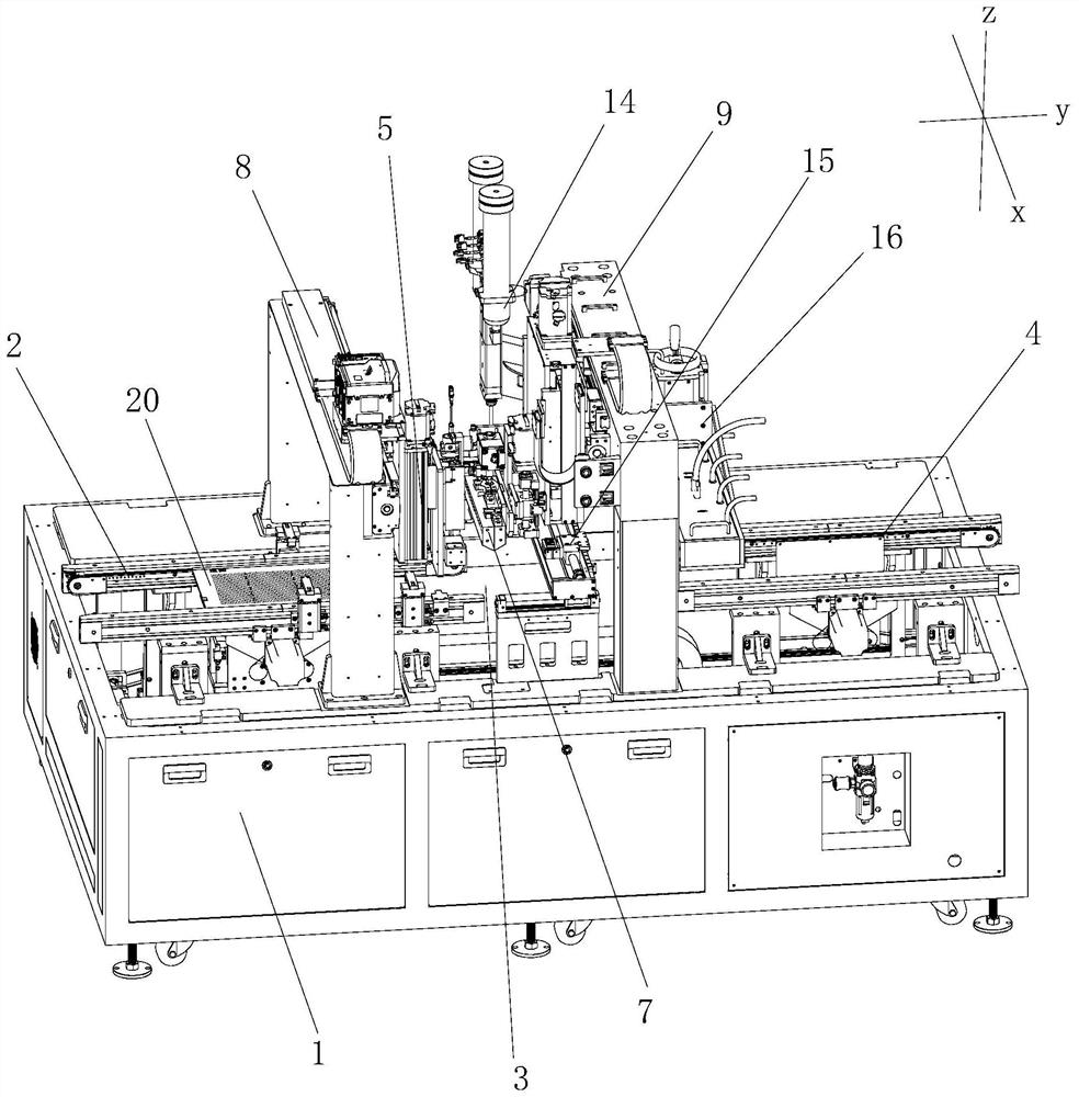
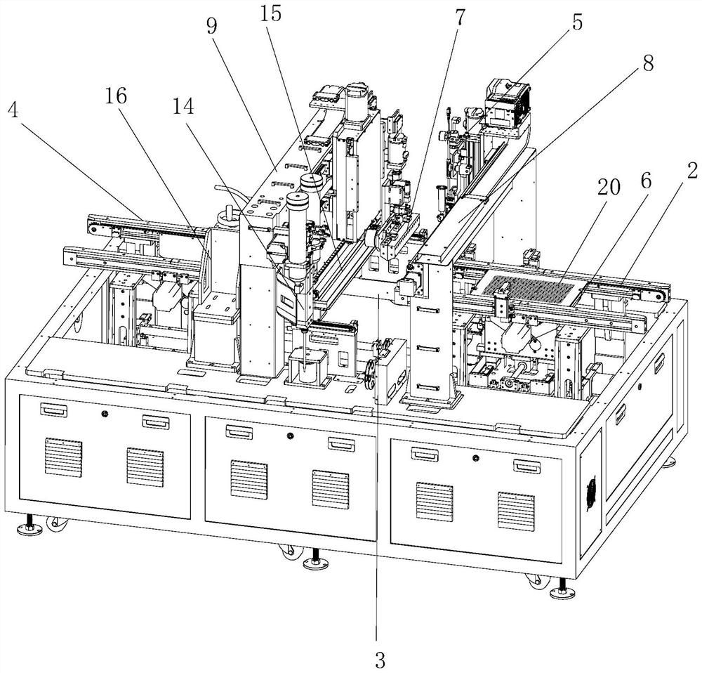
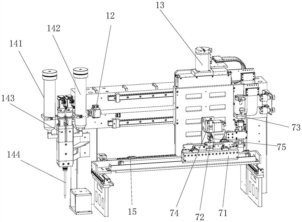
[0035] refer to Figure 1-12 As shown, as an embodiment of the present invention, a coating device is provided, including a base platform 1, a feeding assembly 2, an alignment conveying area 3, a feeding assembly 4, a glue dispensing mechanism 5 and a coating mechanism 7, defining the base The length direction of the table 1 is the y-axis direct...


PUM


Abstract

The invention discloses a coating device which comprises a base table, a feeding assembly, an alignment conveying area, a discharging assembly, a dispensing mechanism and a coating mechanism. An alignment conveying assembly is arranged on the alignment conveying area and used for conducting alignment conveying on products. The feeding assembly is located at the conveying front end of the alignment conveying area and is in butt joint with the alignment conveying assembly, and the discharging assembly is located at the conveying tail end of the alignment conveying area and is in butt joint with the alignment conveying assembly. A first gantry support and a second gantry support are sequentially arranged above the middle of the alignment conveying area in the conveying direction, the dispensing mechanism is arranged on the first gantry support, the coating mechanism is arranged on the second gantry support and comprises a coating tool bit, a rotating head and a tool bit lifting adjusting assembly, and the rotating head and the tool bit lifting adjusting assembly are in transmission connection with the coating tool bit. The rotating head is used for adjusting the horizontal position of the coating tool bit, and the tool bit lifting adjusting assembly is used for adjusting the height position of the coating tool bit. The position of the coating tool bit can be automatically compensated and adjusted, so that the coating and dispensing effects of a product are better.

Description

technical field [0001] The invention relates to the technical field of coating, in particular to a coating device. Background technique [0002] Mini LED refers to LED devices with a chip size between 50 and 200 μm. With the rapid development of Mini LED display technology, Mini LED display products have begun to be used in ultra-large-screen high-definition displays, such as monitoring and command, high-definition broadcasting, high-end theaters, medical diagnosis, advertising display, conferences and exhibitions, office displays, virtual reality and other commercial fields . [0003] The coating method of Mini LED in the prior art is generally to place the PCB board on the alignment platform, and the equipment drives the coating head of the coating mechanism to move back and forth along the PCB board to coat the glue on the PCB board. Since there is no setting Correspondingly adjust the position of the coating cutter head and the parts of the glue outlet pressure, which ...

Claims


Application Information

Patent Timeline
Patent Type & Authority Applications(China)
IPC IPC(8): B05C5/02B05C11/00B05C11/10B05C13/02
CPCB05C5/0254B05C11/1013B05C11/1026B05C13/02B05C11/00
Inventor 陈勇庆罗少斌王金勇
Owner XIAMEN LIJU AUTOMATION TECH
Learn More