Clamping device for aluminum profile machining

A technology of aluminum profile processing and clamping device, which is applied in the field of aluminum profile processing, can solve the problems of uneven processing surface, damage of processing equipment, vibration of aluminum profile, etc., and achieve the effect of improving dimensional accuracy, reducing production cost and improving production efficiency

Inactive Publication Date: 2022-04-29
江苏高卡轻合金有限公司
View PDF0 Cites 1 Cited by
  • Summary
  • Abstract
  • Description
  • Claims
  • Application Information

AI Technical Summary

Problems solved by technology

[0003] In the traditional processing of aluminum profiles, such as cutting and punching, roller shaft equipment is generally used to cooperate with conveying processing. On the one hand, the stability of the conveying process of this equipment is poor, and

Method used


Image

  • Clamping device for aluminum profile machining
  • Clamping device for aluminum profile machining
  • Clamping device for aluminum profile machining

Examples


Embodiment 1

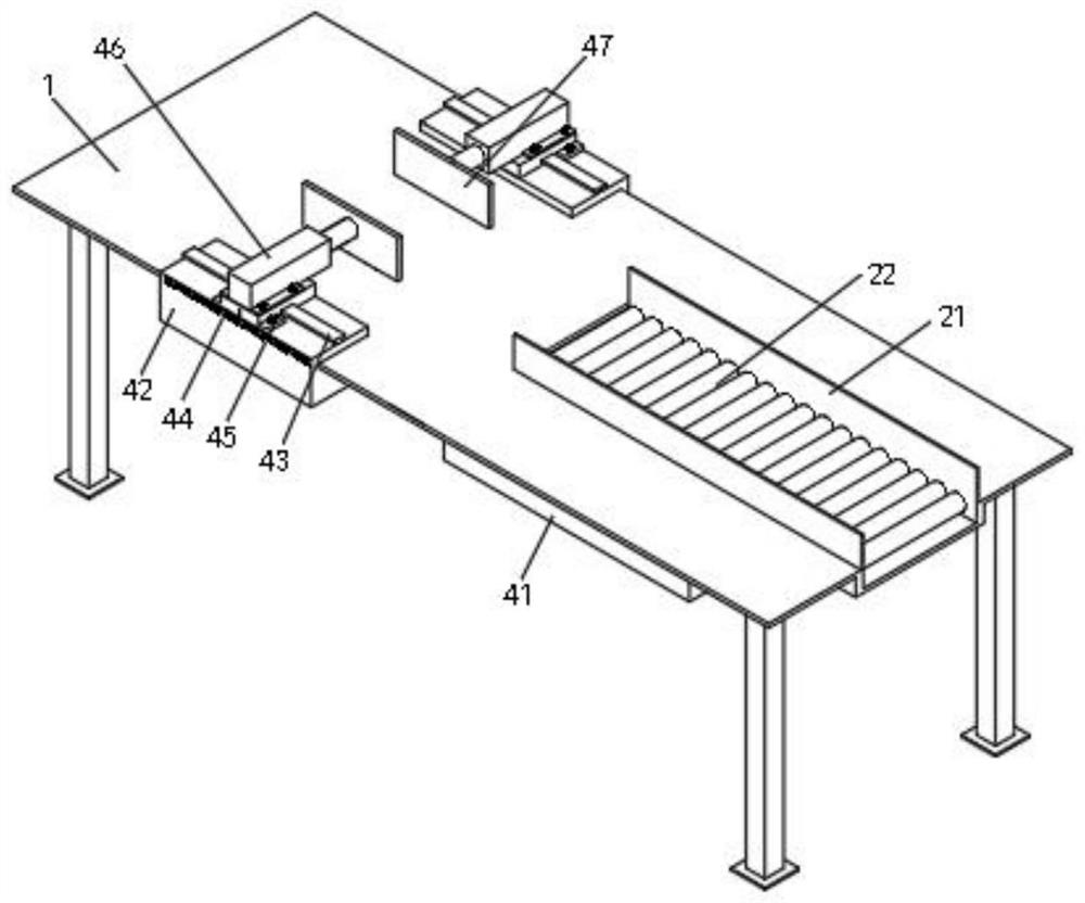
[0033] Such as Figure 1-Figure 3 As shown, in this embodiment, a clamping device for processing aluminum profiles is used to cooperate with aluminum profile processing devices to improve the accuracy of aluminum profile processing, such as aluminum profile cutting devices and punching devices. Conveyor platform 1 of the aluminum profile processing production line. The end of the conveyor platform 1 facing the incoming direction of aluminum profiles is equipped with a roller shaft conveying part. The roller shaft conveying part is composed of the first conveying roller shaft 22 and the limit plate 21, which is used to undertake the upper road. For the aluminum profiles transferred in the process, the conveying track of the aluminum profiles can be preliminarily restricted by the limiting plate 21 .

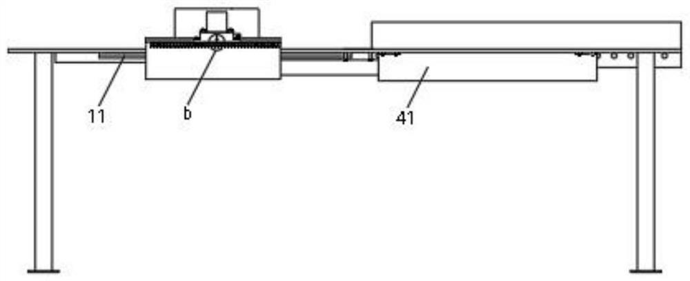
[0034] Certainly, in this embodiment, the height of the axial surface of the first conveying roller shaft 22 protruding from the upper end surface of the conveying platform 1 is 0...

Embodiment 2

[0040] Such as Figure 4-Figure 8 As shown, in this embodiment, a clamping device for aluminum profile processing, the device is used to cooperate with aluminum profile processing devices to improve the accuracy of aluminum profile processing, such as aluminum profile cutting devices, punching devices, the device includes installation On the conveying table 1 of the aluminum profile processing production line, the end of the conveying table 1 facing the incoming direction of the aluminum profile is equipped with a roller conveying part. The roller conveying part is composed of a first conveying roller 22 and a limit plate 21 for receiving The aluminum profiles transferred in the first working procedure can preliminarily restrict the conveying track of the aluminum profiles through the limiting plate 21.

[0041] Certainly, in this embodiment, the height of the axial surface of the first conveying roller shaft 22 protruding from the upper end surface of the conveying table 1 is...


PUM


Abstract

The invention discloses a clamping device for aluminum profile machining, and relates to the technical field of aluminum profile machining. The device comprises a conveying table, the conveying table is provided with a roll shaft conveying part, and the conveying table is further provided with a clamping part arranged in the aluminum profile conveying direction; the clamping part comprises a first sliding rail arranged on the lower end face of the conveying table and a second air cylinder installed on the lower end face of the conveying table, a sliding seat is slidably connected to the first sliding rail, the output end of the second air cylinder is fixedly connected with the sliding seat, a second sliding rail is arranged on the sliding seat, a sliding block is installed on the second sliding rail, and a fixing lug is arranged at the bottom of the sliding block. A screw is in threaded connection with the fixing lug and abuts against the sliding base so that the sliding block can be fixed to the sliding base, a third air cylinder is installed at the upper end of the sliding block, and a second baffle is fixed to the output end of the third air cylinder. According to the clamping device, the aluminum profile is clamped and moved in a clamping mode, it is guaranteed that the transferring distance of the aluminum profile is kept stable, the machining precision of the aluminum profile is improved, the production efficiency is improved, and the production cost is reduced.

Description

technical field [0001] The invention relates to the technical field of processing aluminum profiles, in particular to a clamping device for processing aluminum profiles. Background technique [0002] Aluminum profiles have the characteristics of small mass and high strength, and have become one of the indispensable raw materials in the automobile manufacturing industry. [0003] In the traditional processing of aluminum profiles, such as cutting and punching, roller shaft equipment is generally used to cooperate with conveying processing. On the one hand, the stability of the conveying process of this equipment is poor, and the aluminum profiles tend to shift during the conveying process. On the other hand, the equipment will produce severe vibration when cutting and punching aluminum profiles, resulting in uneven processing surfaces and even damage to processing equipment. Contents of the invention [0004] The purpose of the present invention is to solve the problems ra...

Claims


Application Information

Patent Timeline
IPC IPC(8): B23Q3/08B23Q7/05B21D28/04
CPCB23Q3/08B23Q7/05B21D28/04B23Q2703/04
Inventor 罗斌刘艳平
Owner 江苏高卡轻合金有限公司
Why Eureka
Try Eureka