Preheating equipment for metal wire hot dip galvanizing process

A metal wire and equipment technology, applied in the field of metal wire hot galvanizing process preheating equipment, can solve the problems of unable to achieve synchronous adjustment, less clamping wheel structure, unadjustable guide frame, etc., to ensure the uniformity of heating, guarantee Stability and accuracy, consistent effect of adjustment angle

Inactive Publication Date: 2022-04-29
南通东升旺机械制造有限公司
View PDF0 Cites 0 Cited by
  • Summary
  • Abstract
  • Description
  • Claims
  • Application Information

AI Technical Summary

Problems solved by technology

[0003] In the existing metal wire preheating equipment, although the clamping structure can be adjusted, only the upper one of the two sets of clamping wheels can be adjusted, and synchronous adjustment cannot be realized. There are certain limitations in the adjustment, and the clamping The structure of the wheel set is less, and it can only pull one metal wire to move at a time, which is inefficient. In the preheating equipment, the guide frame is used to guide the movement of the wire with the clamping structure, but the guide frame is not adjustable, and the effect is mediocre.

Method used


Image

  • Preheating equipment for metal wire hot dip galvanizing process
  • Preheating equipment for metal wire hot dip galvanizing process
  • Preheating equipment for metal wire hot dip galvanizing process

Examples


Embodiment 1

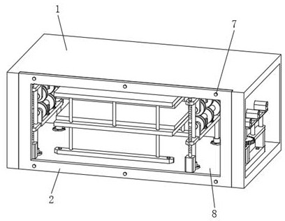
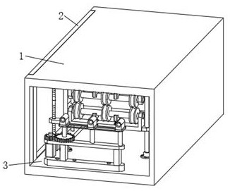
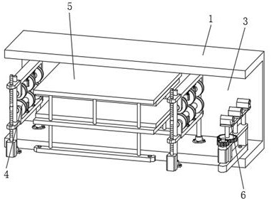
[0031] Such as Figure 1-8 As shown, a metal wire hot galvanizing process preheating equipment includes a main body 1 of the equipment, a side plate 2 is arranged on the main body 1 of the equipment, and an inner cavity 3 is opened on the main body 1 of the equipment, and the inner cavity 3 on the main body 1 of the equipment A heating structure 5 is fixedly installed, and the heating structure 5 includes a mounting plate 501, a support rod 502, a first horizontal plate 503, a second horizontal plate 504, a heating plate 505 and fastening bolts 506, and the support rod 502 is fixed on the mounting plate 501 , the first horizontal plate 503 and the second horizontal plate 504 are installed on the support rod 502, the heating plate 505 is fixedly installed on the first horizontal plate 503 and the second horizontal plate 504, and the inner cavity 3 on the main body 1 of the equipment is provided with a clamp A holding mechanism 4, a guiding structure 6 is fixedly installed in th...

Embodiment 2

[0034] like Figure 1-8 As shown, the components that are the same as or corresponding to those in the first embodiment are marked with the corresponding reference numerals in the first embodiment. For the sake of simplicity, only the differences from the first embodiment will be described below. The difference between this embodiment two and embodiment one is: as Figure 4 , 5 As shown, the clamping mechanism 4 includes a fixed sleeve 401, a guide post 402, a first connecting frame 403, a second connecting frame 404, a rotating shaft 405, a clamping wheel 406, a stabilizing frame 407, a first lifting plate 408, and a second lifting plate 409. The servo motor 410, the screw rod 411, the guide post 402 are arranged on the fixed sleeve 401, and the two sets of rotating shafts 405 are respectively fixed on the first connecting frame 403 and the second connecting frame 404. The two groups of rotating shafts 405 are used in conjunction with each other. The holding wheel 406 is fi...

Embodiment 3

[0037] like Figure 1-8 As shown, the components that are the same as or corresponding to those in the first embodiment are marked with the corresponding reference numerals in the first embodiment. For the sake of simplicity, only the differences from the first embodiment will be described below. The difference between the third embodiment and the first embodiment is: as Figure 7 , 8 As shown, the guide structure 6 includes a connecting rod 601, a welding rod 602, a mounting rod 603, a stepper motor 604, a driving gear 605, a guide frame 606 and a driven gear 607, and the mounting rod 603 is arranged on the upper end of the welding rod 602, stepping The motor 604 is connected with the driving gear 605, and the stepper motor 604 is arranged on the mounting rod 603, the guide frame 606 is installed on the mounting rod 603, the connecting rod 601 and the welding rod 602 are welded together, and the connecting rod 601 There are screws on the top, and the connecting rod 601 is f...


PUM


Abstract

The invention discloses metal wire hot dip galvanizing process preheating equipment which comprises an equipment main body, a side plate is arranged on the equipment main body, an inner cavity is formed in the equipment main body, and a heating structure is fixedly installed in the inner cavity of the equipment main body. The preheating equipment for the metal wire hot dip galvanizing technology belongs to the field of the metal wire hot dip galvanizing technology, a clamping mechanism adopts multiple sets of clamping wheel structures, preheating work of multiple metal wires can be conducted at the same time, a servo motor and a bidirectional lead screw are used, and adjusting work of the upper clamping wheel structure and the lower clamping wheel structure can be conducted synchronously; the stabilizing frame can play a role in supporting the rotating shaft and guarantee stability through structures such as a spring, the guiding structure plays a role in guiding the metal wires and guarantees stability and accuracy of the metal wires during conveying, a stepping motor is arranged in the guiding structure and can conduct angle adjustment, and a linkage rod guarantees synchronous adjustment of all the guiding bases.

Description

technical field [0001] The invention relates to the field of hot galvanizing technology for metal wires, in particular to a preheating equipment for hot galvanizing technology for metal wires. Background technique [0002] Hot enamel, also known as "hot soaking method". The coating method is obtained by directly immersing workpieces such as iron wires, water pipes, iron sheets, etc. into molten metal after chemical treatment. The metal wire hot galvanizing process refers to the process of hot-dip galvanizing the metal wire, which can effectively galvanize the metal wire and ensure the galvanizing effect of the metal wire. In order to improve the galvanizing effect in the hot galvanizing process, it is usually necessary to preheat the metal wire to ensure the rapidity of the subsequent hot enamel process, so it needs to be used in preheating equipment and metal wire preheating equipment , the clamping structure is used to clamp and guide the metal wire, and the pulling mech...

Claims


Application Information

Patent Timeline
Patent Type & Authority Applications(China)
IPC IPC(8): C23C2/02C23C2/06C23C2/38
CPCC23C2/003C23C2/02C23C2/06C23C2/38
Inventor 沈晶冯爱琴
Owner 南通东升旺机械制造有限公司
Why Eureka
Try Eureka