
Building template connecting frame for civil engineering

A construction formwork and civil engineering technology, which is applied to formwork/formwork/work frame connectors, formwork/formwork/work frame, construction, etc., can solve the problems of large load, increase the cost of column pouring, etc., and achieve improvement quality, reduce pouring construction costs, and improve convenience

Inactive Publication Date: 2022-04-29
PUYANG VOCATIONAL & TECHN COLLEGE
View PDF0 Cites 2 Cited by
  • Summary
  • Abstract
  • Description
  • Claims
  • Application Information

AI Technical Summary

Problems solved by technology

At present, when building formwork is used for column pouring, the support structure is usually built layer by layer, and a complex barrel-shaped support frame is formed on the outside of the column; since the load of the concrete and construction load on the supporting panel is radially outward, The load of each layer of support structure will gradually concentrate on the bottom of the barrel-shaped support frame, so that the outward load of the bottom of the barrel-shaped support frame is extremely large; in order to improve the stability of the building formwork, it is necessary to add additional support at the bottom of the barrel-shaped support frame. Greatly increased the cost of column pouring; therefore, there is an urgent need for a building formwork connector for civil engineering

Method used


Image

  • Building template connecting frame for civil engineering
  • Building template connecting frame for civil engineering
  • Building template connecting frame for civil engineering

Examples


Embodiment 1

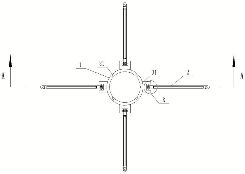
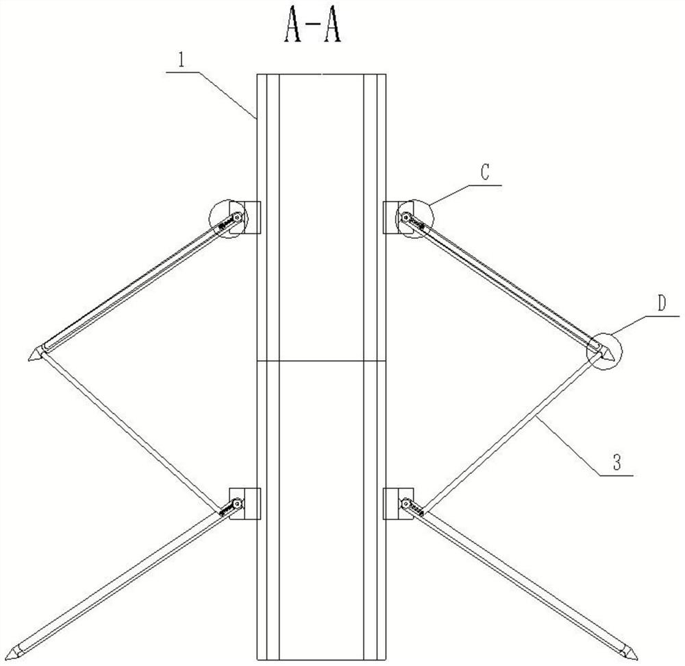
[0020] Such as figure 1 As shown, a building formwork connector for civil engineering, including: a plurality of column pouring tubes stacked sequentially from bottom to top and coaxial with each other, and adjacent tubular formworks are connected to each other to form a multi-layer column pouring formwork; The column pouring pipe includes: a plurality of arc-shaped panels 1, and the adjacent arc-shaped panels 1 are connected to each other; the support assembly is arranged on the outside of the column pouring pipe, and is used to support the column pouring pipe and Its outward load is transmitted downward; the support assembly includes: a plurality of support arms 2, which are evenly arranged on the outside of the curved panel 1, and one end of the support arm 2 is hinged to the curved panel 1; the connecting arm 3 is set On the support arm 2, one end of the connecting arm 3 is connected to the support arm 2, and the other end is connected to the support arm 2 of the upper col...

Embodiment 2

[0022] In order to further improve the pouring efficiency of the column, the installation groove of the adjustment mechanism is used in conjunction with the connecting arm to facilitate the storage and angle adjustment of the connecting arm, so that the curved panels of different height specifications can be flexibly selected for construction during column construction. At the same time, it is used in conjunction with the groove at the bottom of the support arm, which facilitates the installation of the support arms and connecting arms of the upper and lower floors, and further improves the construction convenience of column pouring.

[0023] Such as figure 2 As shown, preferably, the adjustment mechanism includes a mounting groove 21 provided on the support arm 2, one end of the connecting arm 3 is embedded in the installation groove 21 near the side of the curved panel 1 and hinged to its inner wall, and the support arm 2 is away from the The bottom of one end of the curved...

Embodiment 3

[0028] In order to further improve the construction stability, the hexagonal prism is used in conjunction with the third shaft to adjust the angle of the connecting arm and the support arm according to the height specifications of the upper and lower building formwork and then lock it to avoid shaking during construction.

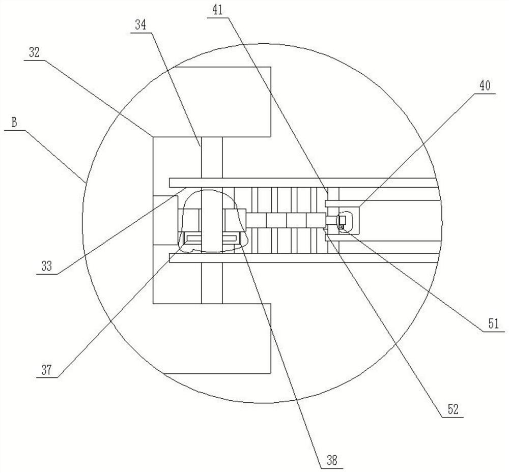
[0029] Preferably, the third gear 44 is pierced with a third rotating shaft 51 and is fixedly connected to it. The two ends of the third rotating shaft 51 are rotationally connected with the inner wall of the installation chamber 43 through bearings. The central axis of the third rotating shaft 51 and the installation chamber The inner wall of 43 is provided with a penetrating limiting hole 52, and the limiting hole 52 is provided with a hexagonal prism 53, which is connected with the third rotating shaft 51 and the support arm 2 respectively, and one end of the hexagonal prism 53 is provided with a handle 54 And fixedly connected with it.


PUM


Abstract

The invention relates to a building template connecting frame for civil engineering, which belongs to the technical field of building column body pouring equipment, and comprises a plurality of arc-shaped panels and a supporting assembly arranged on the outer side of a column body pouring pipe and used for supporting the column body pouring pipe and downwards transmitting an outward load of the column body pouring pipe; the supporting assembly comprises a plurality of supporting arms evenly arranged on the outer side of the arc-shaped panel and connecting arms arranged on the supporting arms, one ends of the connecting arms are connected with the supporting arms, and the other ends of the connecting arms are connected with the supporting arms of the upper-layer column pouring pipe. The supporting arms and the connecting arms of the supporting assemblies are used in cooperation to form a supporting triangle, so that outward loads generated by a top-layer column pouring pipe during concrete pouring construction are partially decomposed and transmitted downwards, the outward loads of the multi-layer stand column pouring formwork are reduced, the accumulated outward loads at the bottom of the supporting frame can be reduced, and the construction efficiency is improved. A support frame is prevented from being added at the bottom of the support frame; the device is convenient to use, easy to operate, high in practicability and worthy of popularization.

Description

technical field [0001] The invention belongs to the technical field of building column pouring equipment, and in particular relates to a building formwork connecting frame for civil engineering. Background technique [0002] Building formwork is a temporary support structure, built according to architectural design requirements, so that concrete structures and components are formed according to the specified position and geometric size, maintain their correct positions, and bear the weight of building formwork and external loads acting on it. The purpose of formwork engineering is to ensure the quality of concrete engineering and construction safety, speed up the construction progress and reduce engineering costs. The building formwork structure that present pouring concrete structure engineering construction is mainly made up of support panel, support structure. The supporting panel is a load-bearing slab that directly contacts the freshly poured concrete, and the supporti...

Claims


Application Information

Patent Timeline
Patent Type & Authority Applications(China)
IPC IPC(8): E04G13/02E04G17/00
CPCE04G13/02E04G17/00
Inventor 刘净利郝慧敏耿烨张玉龙吕伟玲张松涛王士迪
Owner PUYANG VOCATIONAL & TECHN COLLEGE
Learn More