Combined optical fiber connector

A fiber optic connector and combined technology, applied in the field of communication, can solve the problems of irregular depression, deep middle part, complicated polishing process, etc., and achieve the effect of good quality and easy control

Inactive Publication Date: 2022-04-29
ADF FIBERCOM LTD
View PDF5 Cites 0 Cited by
  • Summary
  • Abstract
  • Description
  • Claims
  • Application Information

AI Technical Summary

Problems solved by technology

[0004] In this optical fiber depression is formed by polishing, the polishing process is complicated, and the polished depression is not regular, its edge is shallow, and the middle part is deep
Such a polishing effect is not good

Method used


Image

  • Combined optical fiber connector
  • Combined optical fiber connector
  • Combined optical fiber connector

Examples


Embodiment Construction

[0022] In order to further illustrate the various embodiments, the present invention provides accompanying drawings, which are part of the disclosure of the present invention, and are mainly used to illustrate the embodiments, and can be used in conjunction with the relevant descriptions in the specification to explain the operating principles of the embodiments, for reference Those of ordinary skill in the art should be able to understand other possible implementations and advantages of the present invention. The components in the figures are not drawn to scale, and similar component symbols are generally used to represent similar components.

[0023] The specific embodiments of the present invention will be further described below in conjunction with the accompanying drawings. It should be noted here that the descriptions of these embodiments are used to help understand the present invention, but are not intended to limit the present invention. In addition, the technical fea...


PUM


Abstract

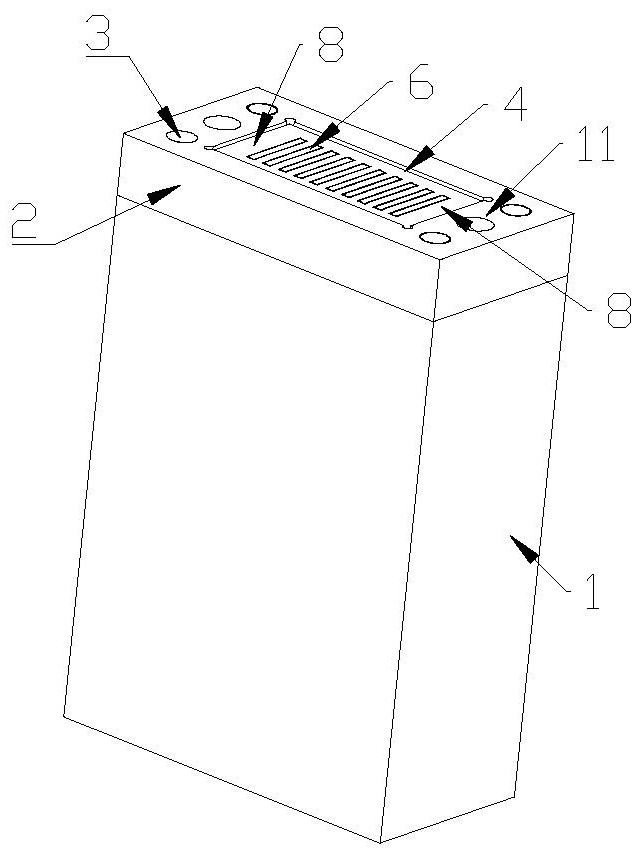
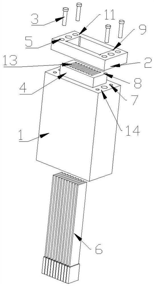
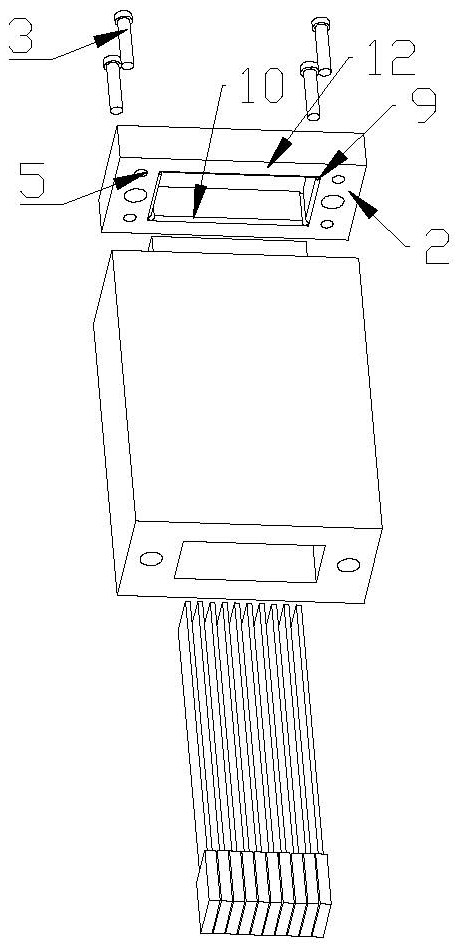
The invention discloses a combined optical fiber connector which comprises an insertion core, an annular lantern ring and a fixing piece, a protrusion is arranged in the middle of the top face of the insertion core, the insertion core is provided with fixing holes around the protrusion, the lantern ring is provided with a fixing piece through hole, and an optical fiber and glue are polished to be flush with the outer side face of the insertion core at the protruding part of the outer side face of the insertion core. The sleeve ring can be sleeved on the protrusion in the middle of the insertion core, the fixing piece penetrates through the fixing piece through hole to be connected with the fixing hole so as to fix the sleeve ring on the insertion core, the thickness of the sleeve ring is larger than the height of the protrusion so as to enable the outer side face of the insertion core to form an optical fiber recess relative to the sleeve ring top face of the sleeve ring, and the sleeve ring top face of the sleeve ring is 2.5-5.0 micrometers higher than the outer side face of the insertion core. The beneficial effects of the technical scheme are that the ferrule is sleeved with the lantern ring, the lantern ring is larger than the height of the protrusion on the ferrule to form the optical fiber recess, compared with the optical fiber recess formed by polishing, the optical fiber recess is easy to control, the recess size is regular, and the phenomenon that the middle is low and the edge is high is avoided.

Description

technical field [0001] The invention relates to the technical field of communication, in particular to a combined optical fiber connector. Background technique [0002] As the optical communication industry continues to advance, more and more optical fibers are used. However, fiber optic connectors are very sensitive to dust. For this reason, the non-contact fiber optic connector was invented by Suzhou Lightas Co., Ltd., which has superior performance and improved a number of technical indicators, such as improving the life of the fiber optic connector and improving the repeatability of plugging and unplugging. 10 times higher, anti-dust and anti-dirt, reduced insertion loss, improved return loss, and can be freely inter-plugged with the connector. However, the structure of this non-contact optical fiber connector is complex, and the depth of the optical fiber depression is too wide. It consists of two parts, one is the metal chip at the front end, and the other is the plas...

Claims


Application Information

Patent Timeline
Patent Type & Authority Applications(China)
IPC IPC(8): G02B6/38
CPCG02B6/3863
Inventor 王网喜冷小冬叶聿村
Owner ADF FIBERCOM LTD
Why Eureka
Try Eureka