Eureka AIR delivers breakthrough ideas for toughest innovation challenges, trusted by R&D personnel around the world.

Stator core fixing structure of axial magnetic field motor

A stator core and axial magnetic field technology, applied in the direction of magnetic circuit shape/style/structure, magnetic circuit static parts, etc., can solve the problem of affecting the stability of the stator core, affecting the operating performance of the motor, and poor stability of the stator core, etc. problems, achieving fast and convenient assembly, improving stability and reliability, and low equipment cost

Pending Publication Date: 2022-04-29
SHANGHAI PANGOOD POWER TECH CO LTD
View PDF9 Cites 0 Cited by
  • Summary
  • Abstract
  • Description
  • Claims
  • Application Information

AI Technical Summary

Problems solved by technology

[0004] The splicing between multiple iron core blocks and the installation of the iron core blocks on the casing will affect the stability of the formed stator core. The formed stator core has poor stability, which will not only deform due to vibration and other factors, but also affect the operating performance of the motor

Method used


Image

  • Stator core fixing structure of axial magnetic field motor
  • Stator core fixing structure of axial magnetic field motor
  • Stator core fixing structure of axial magnetic field motor

Examples


no. 1 example

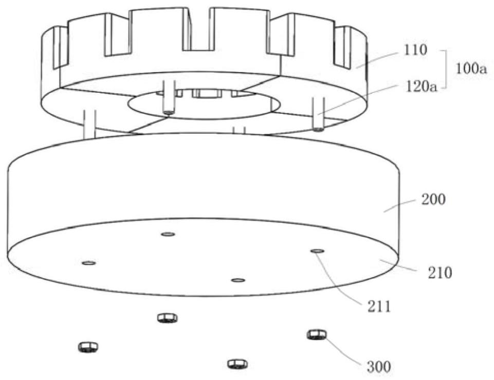
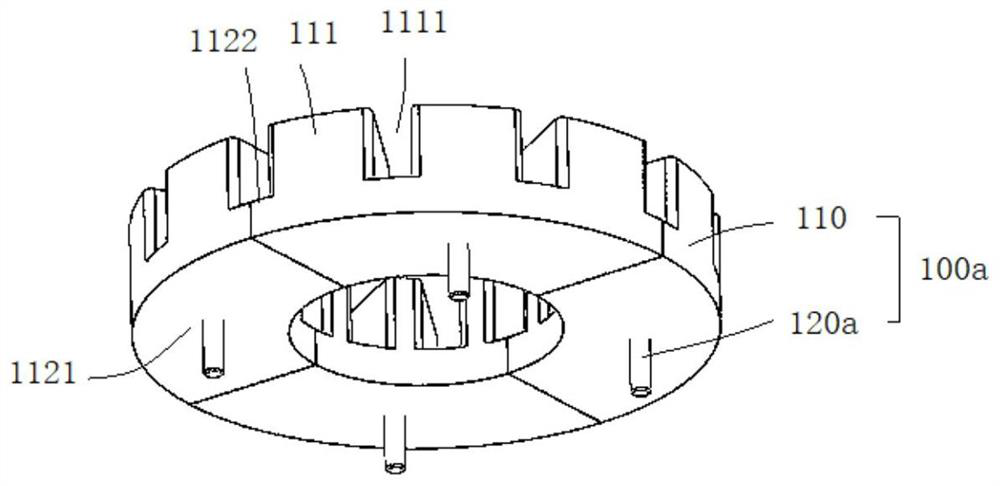
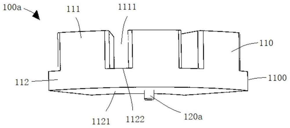
[0048] Such as Figure 1 to Figure 4 As shown, the stator core fixing structure of the axial field motor includes:

[0049] At least one iron core block 100a, the iron core block 100a includes an iron core body 110 and a connecting piece 120a, the connecting piece 120a extends outward and is integrally pressed and formed on the iron core body 110;

[0050] A casing 200, the casing 200 includes a casing bottom plate 210, the casing bottom plate 210 is provided with casing connection holes 211, the number of the casing connection holes 211 is consistent with the number of the connecting parts 120a, and one-to-one correspondence;

[0051] The iron core blocks 100a are fixed on the casing bottom plate 210 in a manner that the connecting piece 120a is connected to the casing connecting hole 211, so that the iron core blocks 100a are spliced ​​along the circumferential direction to form a stator iron. core.

[0052] The connecting piece 120a can be a screw, which includes a conne...

no. 2 example

[0061] Such as Figure 5 to Figure 8 As shown, the stator core fixing structure of the axial field motor includes:

[0062] At least one iron core block 100b, the iron core block 100b includes an iron core body 110 and a connecting piece 120b, the connecting piece 120b extends outward and is integrally pressed and formed on the iron core body 110;

[0063] A casing 200, the casing 200 includes a casing bottom plate 210, the casing bottom plate 210 is provided with casing connection holes 211, the number of the casing connection holes 211 is consistent with the number of the connecting parts 120b, and one-to-one correspondence;

[0064] The iron core segments 100b are fixed on the casing bottom plate 210 by connecting the connecting piece 120b to the casing connection hole 211, so that the iron core segments 100b are spliced ​​along the circumferential direction to form a stator iron core.

[0065] The second embodiment of the stator core fixing structure of the axial field ...

no. 3 example

[0070] Such as Figure 9 to Figure 13 As shown, the stator core fixing structure of the axial field motor includes:

[0071] At least one iron core block 100c, the iron core block 100c includes an iron core body 110 and a connecting piece 120c, the connecting piece 120c extends outward and is integrally pressed and formed on the iron core body 110;

[0072] A casing 200, the casing 200 includes a casing bottom plate 210, the casing bottom plate 210 is provided with casing connection holes 211, the number of the casing connection holes 211 is consistent with the number of the connecting pieces 120c, and one-to-one correspondence;

[0073] The iron core blocks 100c are fixed on the casing bottom plate 210 by connecting the connecting piece 120c to the casing connecting hole 211, so that the iron core blocks 100c are spliced ​​along the circumferential direction to form a stator iron core.

[0074] The second embodiment of the stator core fixing structure of the axial field mo...


PUM


Abstract

The invention provides a stator iron core fixing structure of an axial magnetic field motor, which comprises at least one iron core block, the iron core block comprises an iron core body and a connecting piece, and the connecting piece extends outwards and is integrally pressed and formed on the iron core body; the machine shell comprises a machine shell bottom plate, machine shell connecting holes are formed in the machine shell bottom plate, the number of the machine shell connecting holes is consistent with that of the connecting pieces, and the machine shell connecting holes and the connecting pieces are in one-to-one correspondence; and the iron core blocks are fixed on the casing bottom plate in a manner that the connecting pieces are connected with the casing connecting holes, so that the iron core blocks are spliced along the circumferential direction to form the stator iron core. The connecting piece is integrally formed in the pressing process of the iron core body, the stability of the iron core block structure is guaranteed, manufacturing is simple, the equipment cost is low, assembling is rapid and convenient, it is guaranteed that the iron core body is spliced in the circumferential direction to form the annular stator iron core, the stability and reliability of the formed stator iron core structure are improved, and the service life of the stator iron core is prolonged. And the operation efficiency of the motor is prevented from being influenced.

Description

technical field [0001] The invention relates to the field of axial field motors, in particular to a stator core fixing structure of an axial field motor. Background technique [0002] Axial field motors have the advantages of small axial size, compact structure, high torque density and high efficiency. The axial field motor includes a stator, a rotor and a casing, the stator includes a stator core and coils arranged on the stator core, and the stator core is fixed on the casing by bolts. [0003] At present, the stator core structure mainly adopts SMC (Soft Magnetic Composite) iron core. The SMC iron core is made of high-purity iron powder as the main raw material. . The use of SMC iron core can reduce the size of the motor and reduce the loss. As the torque of the axial magnetic field motor increases, the volume of the iron core also needs to increase accordingly, but limited by the tonnage of the press, the iron core with too large volume cannot be pressed and manufactu...

Claims


Application Information

Patent Timeline
Patent Type & Authority Applications(China)
IPC IPC(8): H02K1/18H02K1/14
CPCH02K1/182H02K1/148H02K2201/12H02K2201/15
Inventor 张广权徐典友高旭刑宏伟
Owner SHANGHAI PANGOOD POWER TECH CO LTD
Why Eureka
Eureka Blog
Learn More