
Fuel gas liquid separation equipment

A fuel gas and liquid separation technology, which is applied in the direction of separation methods, dispersed particle separation, chemical instruments and methods, etc., can solve the problems of high cost, large amount of on-site welding engineering, etc., and achieve the advantages of convenient manufacture, simple structure, and easy purging Effect

Pending Publication Date: 2022-05-03
CHINA PETROLEUM & CHEM CORP +2
View PDF8 Cites 0 Cited by
  • Summary
  • Abstract
  • Description
  • Claims
  • Application Information

AI Technical Summary

Problems solved by technology

[0005] In order to solve the technical problems of large field welding engineering quantity and high cost in the prior art, the present invention provides a fuel gas liquid separation equipment

Method used


Image

  • Fuel gas liquid separation equipment
  • Fuel gas liquid separation equipment
  • Fuel gas liquid separation equipment

Examples


Embodiment Construction

[0022] The present invention will be further described below in conjunction with the accompanying drawings.

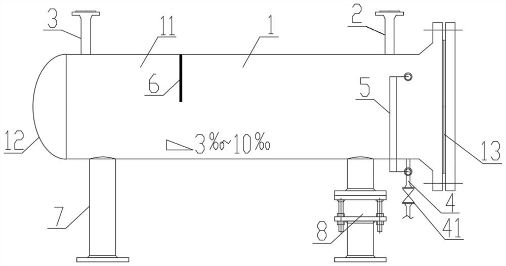
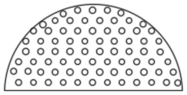
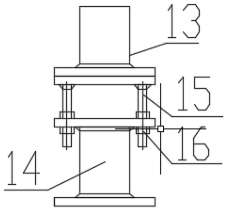
[0023] Such as Figure 1~3 As shown, the fuel gas liquid separation device of the present invention is mainly composed of a tank housing 1, an inlet nozzle 2, an outlet nozzle 3, a liquid discharge nozzle 4, a liquid level gauge 5, a baffle plate 6, a rigid support 7 and Adjustable support 8 forms. The tank shell of the liquid dispensing device slopes downward to the liquid discharge nozzle 4 with a slope of 3‰~10‰.

[0024] The inner diameter of the tank shell 1 is 6-20 times the diameter of the inlet nozzle 2, for example, when the diameter of the fuel gas inlet is DN80, the inner diameter of the tank shell 1 is 480-1600. The tank shell 1 is composed of a cylinder body 9 in the middle, pipe caps 10 at both ends, and a sealing structure 11 between the flange and the flange cover. The sealing structure of the flange and the flange cover is convenient for cleaning th...


PUM

PropertyMeasurementUnit
Heightaaaaaaaaaa

Abstract

The invention discloses fuel gas liquid separation equipment. The equipment comprises a tank shell, an inlet pipe nozzle, an outlet pipe nozzle, a liquid discharge pipe nozzle and a support, the middle part of the tank shell is a horizontal cylinder, one end is welded with a pipe cap, and the other end is a sealing structure of a flange and a flange cover; the inlet pipe nozzle and the outlet pipe nozzle are both located at the top of the tank shell and communicated with the tank shell, and flanges are arranged at the ends of the inlet pipe nozzle and the outlet pipe nozzle. The liquid discharge pipe nozzle is positioned on one side close to the flange sealing structure end of the tank shell and is positioned at the bottom of the shell; the support comprises a rigid support and an adjustable support which are both welded to the bottom of the tank shell, and the adjustable support is adjusted to enable the whole liquid separation device to go downwards to the liquid outlet with the gradient of 3% o-1% o. One end of the equipment adopts a sealing structure of a flange and a flange cover, so that the equipment can be conveniently purged, cleaned and maintained, the whole tank shell of the equipment can be manufactured by adopting standard pipeline elements, the structure is simple, the manufacturing is convenient, and liquid level meters are arranged on a liquid discharge pipe nozzle and the tank shell, so that the condensate condition in the equipment can be conveniently monitored.

Description

technical field [0001] The invention belongs to the field of petroleum processing, and relates to equipment for buffering and purifying fuel gas to remove condensed liquid therein, in particular to a fuel gas liquid separation equipment. Background technique [0002] In petrochemical installation enterprises, the fuel gas from the system or production device is often divided into two routes. The main fuel gas passes through a vertical separator tank, buffered and purified, and then connected to the burner of the heating furnace; the fuel gas on the furnace burner The fuel gas for the lamp does not pass through the vertical liquid separation tank, but passes through a tubular liquid separation section formed by multiple diameter reductions of the pipeline, in which condensed liquid or water is precipitated. The use of this tubular liquid separation section requires 3 to 5 stages of diameter expansion to the required liquid separation diameter, and then 3 to 5 stages of diamet...

Claims


Application Information

Patent Timeline
IPC IPC(8): B01D53/26B01D45/08
CPCB01D53/26B01D45/08
Inventor 陈杰朱玥丁磊王金富郭兆阳王志中牛存厚
Owner CHINA PETROLEUM & CHEM CORP
Learn More