
Suspension type high-position oil collecting device used in fixed top storage tank

An oil collecting device and suspension type technology, applied in the field of suspension type high-level oil collecting device, can solve the problems of inability to discharge oil, inaccurate overflow liquid level, large circumferential installation error, etc., to protect the environment, The effect of good oil drainage and low cost

Pending Publication Date: 2020-04-07
CHINA PETROLEUM ENG & CONSTR +3
View PDF0 Cites 0 Cited by
  • Summary
  • Abstract
  • Description
  • Claims
  • Application Information

AI Technical Summary

Problems solved by technology

In the prior art, the ubiquitous problems of the oil collecting device are large circumferential installation error, inaccurate overflow liquid level and unable to drain the oil completely.

Method used


Image

  • Suspension type high-position oil collecting device used in fixed top storage tank
  • Suspension type high-position oil collecting device used in fixed top storage tank

Examples


Embodiment 1

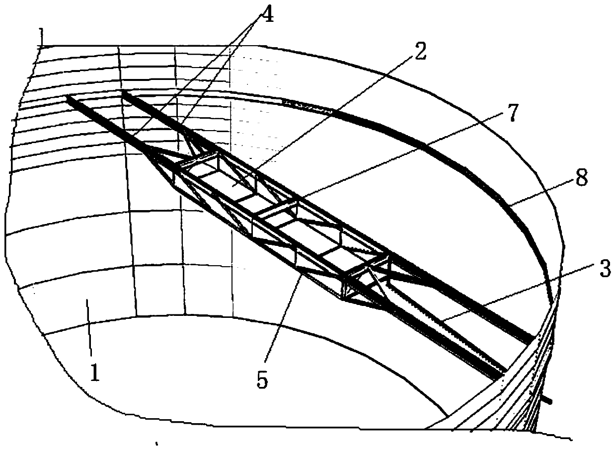
[0030] On the basis of the above structure, in this embodiment, the upper part of the storage tank 1 is provided with a cantilever hanger 4, and the cantilever hanger 4 includes two suspension rods arranged side by side on the upper part of the storage tank 1, and each suspension rod The two ends of the tank are welded together with the inner wall of the storage tank 1 respectively; the oil sump 2 is fixedly installed on the cantilever hanger 4, usually by welding, the structure is simple, and the oil sump 2 is easy to install, saving time and effort.

Embodiment 2

[0032] On the basis of Embodiment 1, in this embodiment, a grid-type bracket 5 is fixedly installed on the cantilever hanger 4, and the bracket 5 is directly welded to the cantilever hanger 4 to form a groove; the oil collection tank 2 is fixedly installed in the groove on the bracket 5 to increase the stability of the oil collecting tank 2; the oil collecting tank 2 is usually fixedly installed on the bracket 5 by welding for easy disassembly. During the oil collection process, since water will generate certain pressure on the oil collection tank 2 during the process of sending water into the storage tank 1, the grid-type bracket 5 protects the oil collection tank 2 and increases the stability of the oil collection tank 2.

Embodiment 3

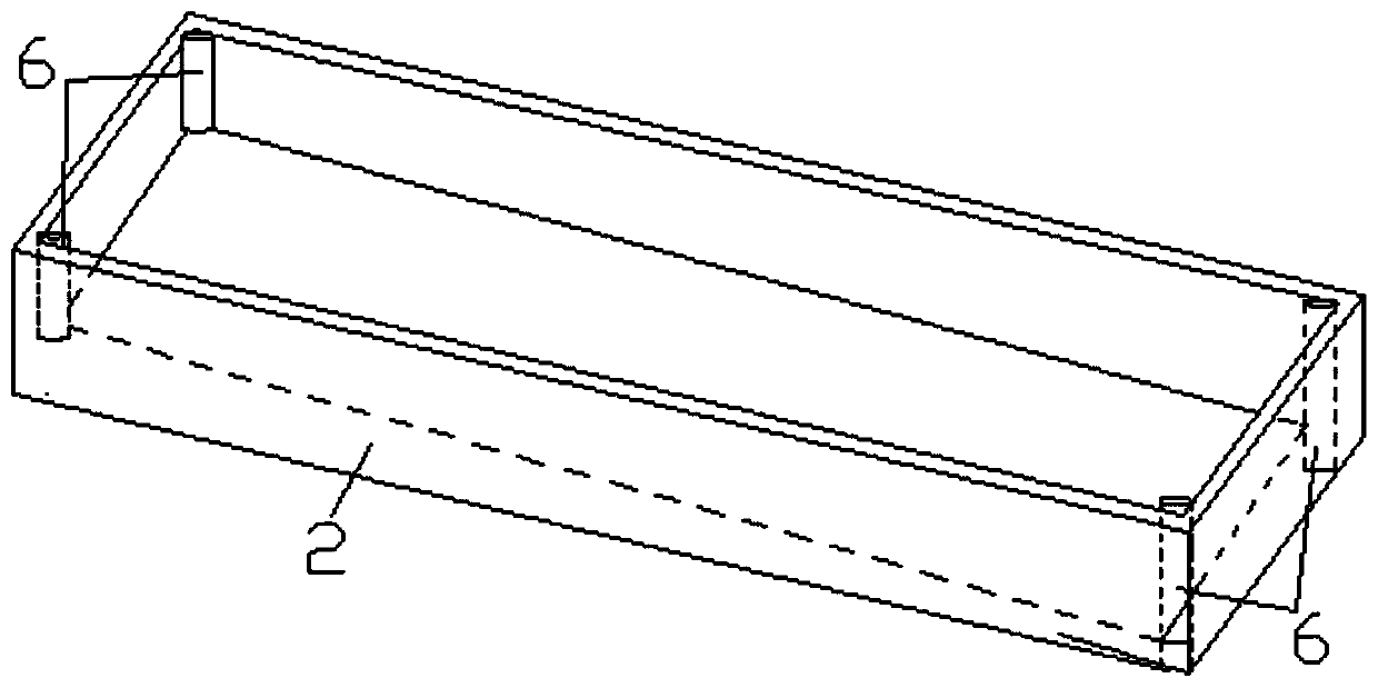
[0034] On the basis of Embodiment 1, in this embodiment, the oil collecting tank 2 is a rectangular tank, and it is installed obliquely on the cantilever hanger 4, so as to facilitate the draining of the oil collected in the oil collecting tank 2 and prevent oil from accumulating in the oil collecting tank 2 Explosion occurs inside, safe and reliable.

[0035] Preferably, in this embodiment, the inclination rate of the oil collection tank 2 is 1:150-200, and the inclination rate is preferably 1:180, which can not only ensure the oil collection volume of the oil collection tank 2, but also ensure that the oil collected in the oil collection tank 2 is drained. do.


PUM


Abstract

The invention relates to a suspension type high-position oil collecting device used in a fixed top storage tank. The device comprises an oil collecting tank erected on the upper portion in the storagetank, the top of the oil collecting tank is open, an oil discharging port is formed in the bottom of the oil collecting tank, the oil discharging port is fixedly connected with one end of an oil discharging pipe, and the other end of the oil discharging pipe penetrates through the side wall of the storage tank and extends out of the storage tank. The oil collecting device has the beneficial effects of simple structure, convenience in disassembly and assembly, better oil drainage effect and lower cost.

Description

technical field [0001] The invention relates to the technical field of oil and gas exploitation, in particular to a suspension type high-level oil collecting device used in a fixed-roof storage tank. Background technique [0002] Large fixed-roof storage tanks are often used for the storage, treatment and discharge of oily sewage on the surface gathering and transportation stations of oil fields. One of its important functions is to let the oily sewage stored in the tank stand still to achieve the accumulation of oil droplets, and set up a separate collection device to discharge the oil out of the storage tank for reprocessing. [0003] At present, the common forms of oil collecting devices used in storage tanks at home and abroad include floating type and side wall type. Due to the increasingly large design of storage tanks at home and abroad, new requirements are constantly put forward for oil collection and oil level control. In the prior art, the ubiquitous problems of...

Claims


Application Information

Patent Timeline
IPC IPC(8): B65D90/00C02F1/40
CPCB65D90/00C02F1/40
Inventor 崔振宁郭树平杨晓通董磊李肖蔚李良平李魏吴家祥吴继尧
Owner CHINA PETROLEUM ENG & CONSTR
Learn More