Packaging box bonding device

A bonding device and packaging box technology, which is applied in the directions of packaging, transportation and packaging, box making operations, etc., can solve the problems of loosening and detachment of packaging box parts, reduce the existence of air bubbles, increase the extrusion effect, and increase the connection. Effect

Inactive Publication Date: 2022-05-03
无锡文教印务有限公司
View PDF10 Cites 0 Cited by
  • Summary
  • Abstract
  • Description
  • Claims
  • Application Information

AI Technical Summary

Problems solved by technology

[0004] In the prior art, in the production of wine box packaging boxes, two different packaging box parts need to be bonded to make them integrated in the subsequent process

Method used


Image

  • Packaging box bonding device
  • Packaging box bonding device
  • Packaging box bonding device

Examples


Embodiment 1

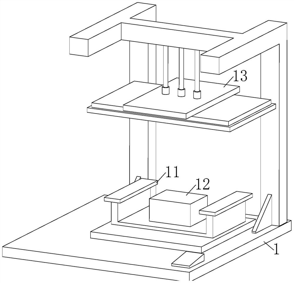
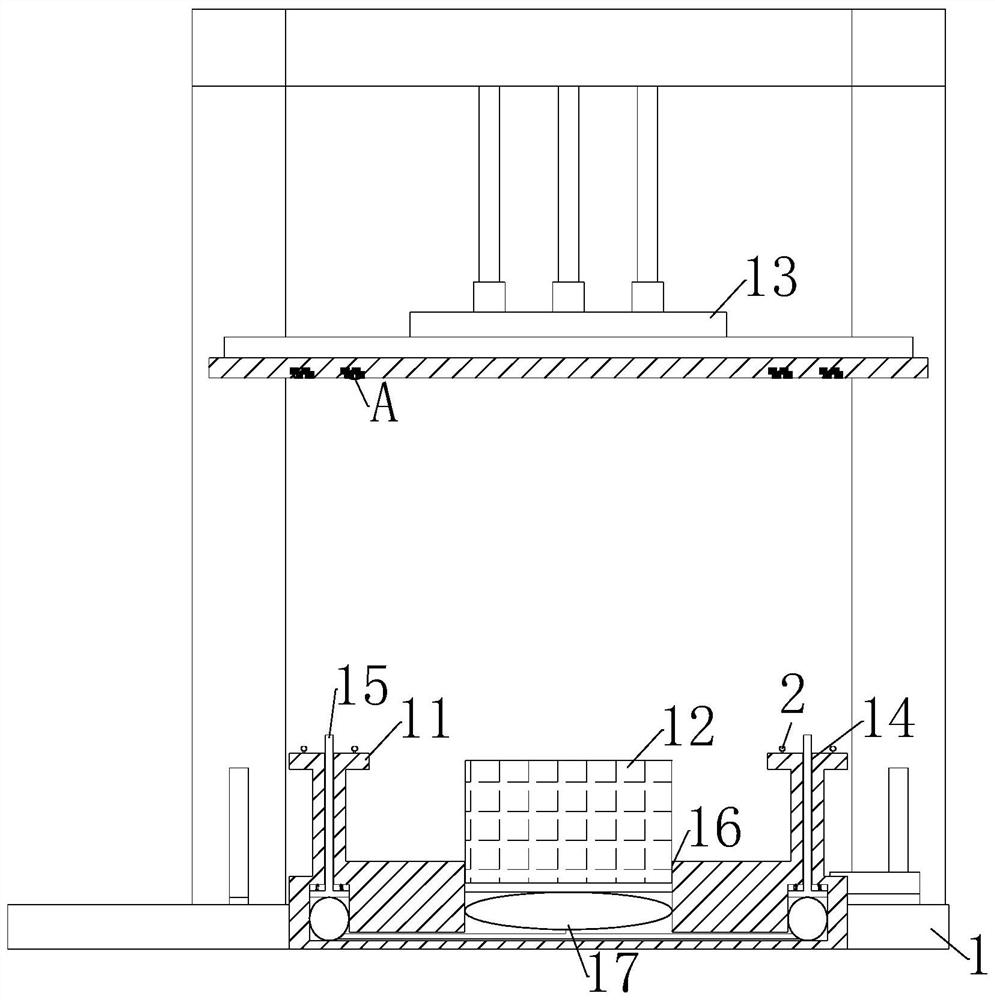
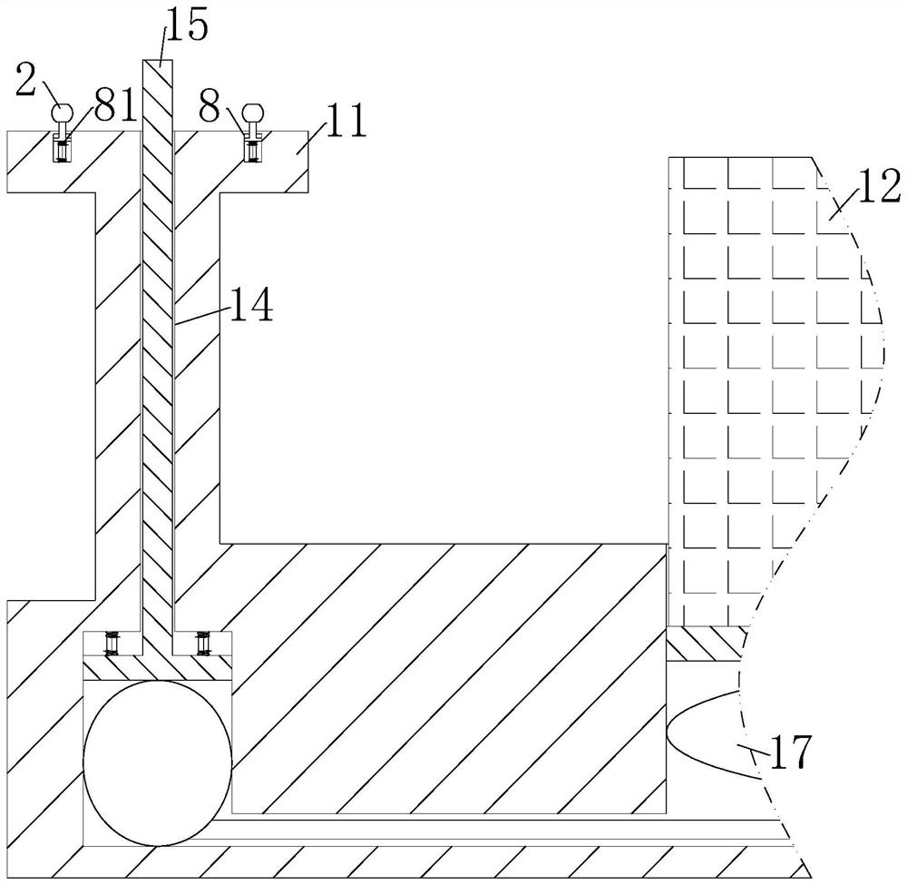
[0030] Such as Figure 1 to Figure 3 As shown, a packaging box bonding device described in the embodiment of the present invention includes a base 1; a pair of No. 1 limiting plates 11 are fixedly connected to the top of the base 1; 13. There is a No. 1 chute 14 at the top of the one-to-one number limiting plate 11; an extrusion rod 15 is slidably connected to the inside of the No. 1 chute 14; the top of the base 1 is located on the one-to-one number limiting plate 11 There is a No. 2 chute 16 between them; the inside of the No. 2 chute 16 is slidingly connected to the limit block 12; the inside of the No. 1 limiting plate 11 and the No. 2 chute 16 are fixedly connected with an air bag 17; The above-mentioned airbags 17 are connected through the air guide tube; when working, the staff will place the base 1 on the designated position, place the packaging box on the limit block 12, and squeeze it through the decline of the No. 1 squeeze plate 13 , the extrusion rod 15 will be s...

Embodiment 2

[0040] Such as Image 6 As shown in Comparative Example 1, another embodiment of the present invention is: a pair of rubber plates 3 bottoms are rotatably connected with cams 101, and arranged symmetrically; during operation, when the connecting ball 2 enters the pair of rubber plates 3, the rotation of the cam 101 can assist the entry of the connection ball 2 and provide guidance. The rotatable cam 101 can guide the connection ball 2, and at the same time, its own protrusion can make the connection ball 2 move forward when entering. Vibration further eliminates the glue bubbles between the two packaging box components, increases the product integrity of the subsequent packaging box during processing, and reduces the subsequent shedding of the two packaging box components.

[0041] When working, when working, the staff will place the base 1 on the designated position, place the packaging box on the limit block 12, squeeze it through the decline of the No. 1 extrusion plate 13,...


PUM


Abstract

The invention belongs to the field of packaging box bonding, and particularly relates to a packaging box bonding device which comprises a base. The top end of the base is fixedly connected with a pair of first limiting plates. The top end of the base is slidably connected with a first extrusion plate. A first sliding groove is formed in the top end of the pair of first limiting plates. An extrusion rod is slidably connected into the first sliding groove. A second sliding groove is formed in the position, between the pair of first limiting plates, of the top end of the base. A limiting block is slidably connected into the second sliding groove. Air bags are fixedly connected into the first limiting plate and the second sliding groove. The multiple sets of air bags are communicated through air guide pipes. Through communication between air bags, when a first extrusion plate extrudes, a limiting block moves upwards, two different packaging box components are extruded up and down at the same time, the extrusion effect is further improved, bubbles existing in glue between the two packaging box components are reduced through extrusion force, and the situation that the two packaging box components fall off subsequently is reduced.

Description

technical field [0001] The invention belongs to the field of bonding of packaging boxes, in particular to a packaging box bonding device. Background technique [0002] Packaging box is a common packaging product in modern society. It can classify and store the produced products to protect the integrity of the product during transportation. At the same time, it is convenient to stack and increase the integrity. It is indispensable in modern society. one of the items. [0003] A Chinese patent with publication number CN111152988B discloses an automatic bonding device for packaging boxes, which includes a first drive mechanism and a second drive mechanism arranged on the workbench. An adsorption mechanism, a fourth drive mechanism, and a fifth drive mechanism are provided at the end of the connecting plate, and a sixth drive mechanism is provided at the bottom of the third drive unit. [0004] In the prior art, in the production of wine box packaging boxes, two different pack...

Claims


Application Information

Patent Timeline
IPC IPC(8): B31B50/62B31B50/74B31B50/00
CPCB31B50/624B31B50/74B31B50/006
Inventor 华保家
Owner 无锡文教印务有限公司
Why Eureka
Try Eureka