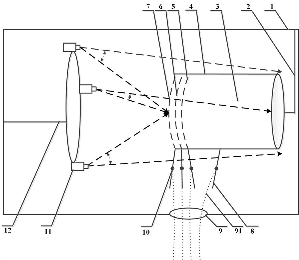
Beam scintillation spatio-temporal evolution monitoring device for ion electric thruster

A technology for ion thrusters and monitoring devices, which is applied to measuring devices, instruments, scientific instruments, etc., can solve problems such as difficult identification of beam scintillation types, unknown time evolution characteristics, and inaccurate positioning of beam scintillation, so as to improve reliability Accuracy, overcoming omission or misjudgment, and precise positioning

Active Publication Date: 2022-05-03
LANZHOU INST OF PHYSICS CHINESE ACADEMY OF SPACE TECH
View PDF6 Cites 0 Cited by
  • Summary
  • Abstract
  • Description
  • Claims
  • Application Information

AI Technical Summary

Problems solved by technology

[0003] The main purpose of this application is to provide an ion electric thruster beam scintillation space-time evolution monitoring device to solve the problems of inaccurate beam scintillation positioning, unknown time evolution characteristics, and difficult interpretation of beam scintillation types in existing ion electric thrusters

Method used


Image

  • Beam scintillation spatio-temporal evolution monitoring device for ion electric thruster

Examples


Embodiment Construction

[0017] In order to enable those skilled in the art to better understand the solution of the present application, the technical solution in the embodiment of the application will be clearly and completely described below in conjunction with the accompanying drawings in the embodiment of the application. Obviously, the described embodiment is only It is an embodiment of a part of the application, but not all of the embodiments. Based on the embodiments in this application, all other embodiments obtained by persons of ordinary skill in the art without creative efforts shall fall within the scope of protection of this application.

[0018] It should be noted that the terms "first" and "second" in the description and claims of the present application and the above drawings are used to distinguish similar objects, but not necessarily used to describe a specific sequence or sequence. It should be understood that the data so used may be interchanged under appropriate circumstances for...


PUM


Abstract

The invention discloses a beam flicker spatio-temporal evolution monitoring device of an ion electric thruster. The device comprises a vacuum chamber, a first support structure for fixing a thruster on the vacuum chamber, an ion thruster, a shell of the thruster, a screen gate electrode, an acceleration gate electrode, a deceleration gate electrode, a lead for connecting the electrodes, a signal line and a flange which are arranged on the wall of the vacuum chamber and are used for transmitting diagnosis information, and a monitoring device for loop volt-ampere characteristic measurement, the high-speed camera array is used for monitoring time-space characteristics of beam flicker; and the second supporting structure is used for fixing and mounting cameras. According to the invention, the problems of precise positioning and time evolution characteristic tracking of the beam flicker space position of the ion electric thruster in a closed and high-vacuum environment are solved, and the problem that the beam flicker generation position and flicker type identification are difficult to determine only by monitoring the volt-ampere characteristics of a loop in the prior art is solved. And secondly, the device can comprehensively monitor the spatial characteristics and the time evolution characteristics of beam flicker.

Description

technical field [0001] The application relates to the field of aerospace electric propulsion technology and the field of industrial low-temperature plasma coating, in particular, to a monitoring device for beam scintillation spatio-temporal evolution of an ion electric thruster. Background technique [0002] The ion thruster for space uses electric energy to ionize the propellant to generate plasma, and extracts, accelerates and discharges ions through a high-voltage grid system to generate thrust. Due to the interaction between plasma, neutral gas and high-voltage electrodes in the working process of the ion thruster, there is inevitably an abnormal beam flicker (unexpected discharge) problem during the working process of the ion thruster, which is serious It will affect the performance and life reliability of the ion thruster. However, since beam scintillation is a millisecond-level transient process, and the location where beam scintillation occurs is also uncertain, usu...

Claims


Application Information

Patent Timeline
Patent Type & Authority Applications(China)
IPC IPC(8): G01T1/29
CPCG01T1/29
Inventor 王润福吴辰宸孙新锋耿海王紫桐蒲彦旭吕方伟李兴达
Owner LANZHOU INST OF PHYSICS CHINESE ACADEMY OF SPACE TECH
Why Eureka
Try Eureka