
A worktable rotary device

A technology of a rotary device and a workbench, which is applied in the field of mechanical equipment, can solve the problems of poor positioning accuracy of the workbench and poor processing quality of the louvers, and achieve the effects of reasonable structure, improved processing quality, and reduced energy consumption

Active Publication Date: 2017-08-18
江苏虹福造船有限公司
View PDF8 Cites 0 Cited by
  • Summary
  • Abstract
  • Description
  • Claims
  • Application Information

AI Technical Summary

Problems solved by technology

[0003] The purpose of the present invention is to provide a worktable rotary device to solve the problem of poor processing quality of the louvers caused by the poor positioning accuracy of the existing workbench

Method used


Image

  • A worktable rotary device
  • A worktable rotary device

Examples


Embodiment Construction

[0014] The present invention will be further described in detail below in conjunction with the accompanying drawings and examples. The following examples are explanations of the present invention and the present invention is not limited to the following examples.

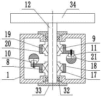
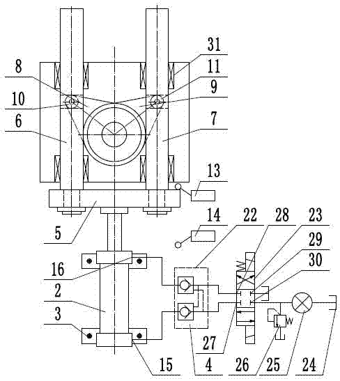
[0015] like figure 1 and figure 2 As shown, a worktable rotary device includes a machine base 1, a driving cylinder 2, a cylinder support 3, a hydraulic system 4, a connecting plate 5, a first sliding rod 6, a second sliding rod 7, a first one-way clutch 8. The second one-way clutch 9, the first roller 10, the second roller 11, the output shaft 12, the first travel switch 13, the second travel switch 14, the workbench 34, the first sliding rod 6 and the second sliding rod The rods 7 are parallel to each other and are all slidably arranged on the support 1. A sliding guide sleeve 31 is arranged between the first slide bar 6 and the support 1, and between the second slide bar 7 and the support 1, so as to reduce Th...


PUM


Abstract

The invention provides a working table rotation device, and belongs to the technical field of mechanical equipment. The working table rotation device comprises a first one-way clutch and a second one-way clutch; a first sliding rod and a second sliding rod are arranged on a machine base in a sliding manner, one end of the first sliding rod and one end of the second sliding rod are both connected to a connecting plate, a piston rod of a drive oil cylinder is connected with the connecting plate, and the axis of an output rotating shaft and the axis of the driving oil cylinder are mutually perpendicular and are located between the first sliding rod and the second sliding rod; a working table is coaxially mounted at one end of the output rotating shaft, a first inner seat ring of the first one-way clutch is fixedly connected to the output rotating shaft, and a first rolling wheel on a first outer sleeve is mounted in a rolling wheel groove of the first sliding rod; and a second inner seat ring of the second one-way clutch is also fixedly connected to the output rotating shaft, a second rolling wheel on the second outer sleeve is mounted in a rolling wheel groove in the second sliding rod, and the idling direction of the first one-way clutch and the idling direction of the second one-way clutch are the same. Precise positioning of the working table can be achieved, and machining quality of an impeller is improved.

Description

technical field [0001] The invention relates to the technical field of mechanical equipment, in particular to a worktable turning device. Background technique [0002] The shutter wheel is a strong elastic grinding disc, which is made of plastic or fiber mesh cover and emery cloth sheets. It is mainly used for grinding and polishing in industrial production, specifically for rust removal, paint removal, deburring and grinding of various types of metal and non-metal materials in shipbuilding, automobiles, aviation, machinery, instruments, bridges and construction industries and furniture. welds. In the automatic production of the louver, the chassis of the louver is placed on the station plate on the slewing mechanism, and is transported to the corresponding station with the rotation of the slewing mechanism. According to the production process of the louver, the louver With the rotation of the slewing mechanism, the chassis of the chassis passes through the gluing station ...

Claims


Application Information

Patent Timeline
Patent Type & Authority Patents(China)
IPC IPC(8): B25H1/14F16D25/10
CPCB25H1/14F16D25/10F16D25/14
Inventor 李丹曾婵何悦
Owner 江苏虹福造船有限公司
Learn More