Wood product sand blasting device
A technology of sandblasting device and wood products, which is applied to explosion generating devices, used abrasive treatment devices, spray guns, etc., can solve the problems of uneven sandblasting, inability to change the sandblasting direction, device vibration, etc., and achieve sandblasting. Uniform, improved quality, improved accuracy
- Summary
- Abstract
- Description
- Claims
- Application Information
AI Technical Summary
Problems solved by technology
Method used
Image
Examples
Embodiment 1
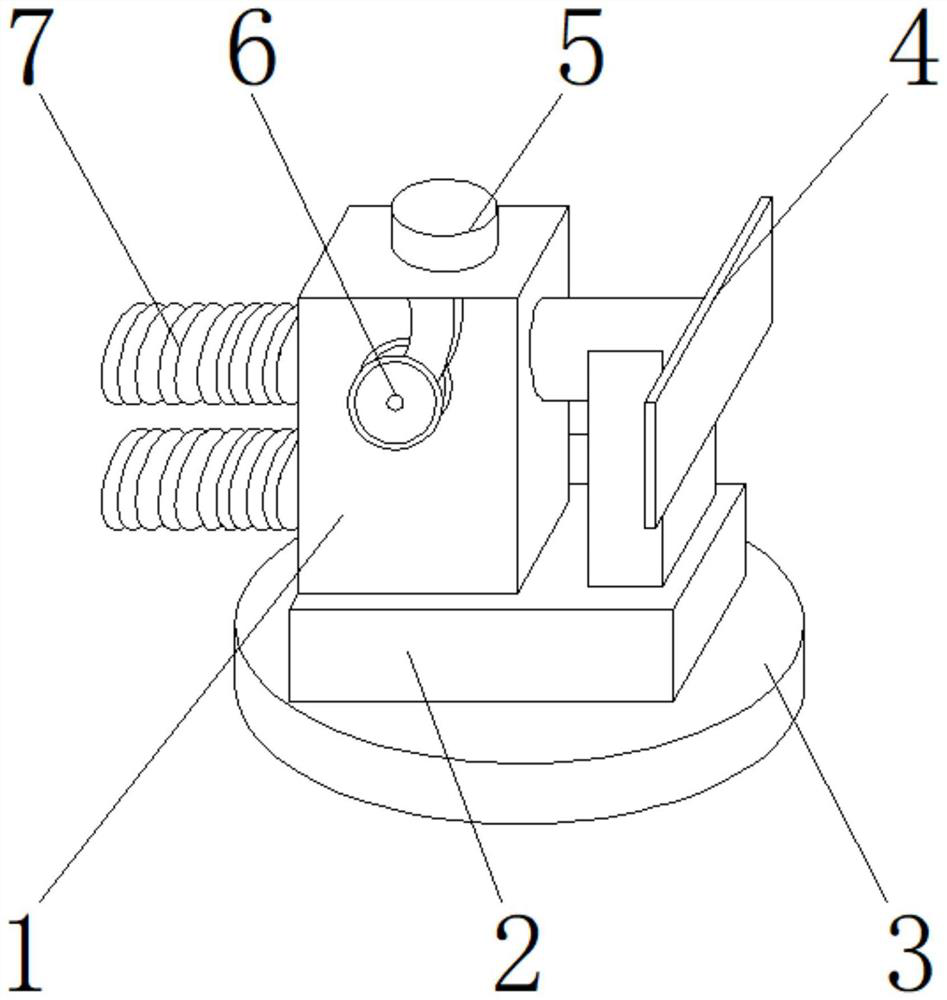
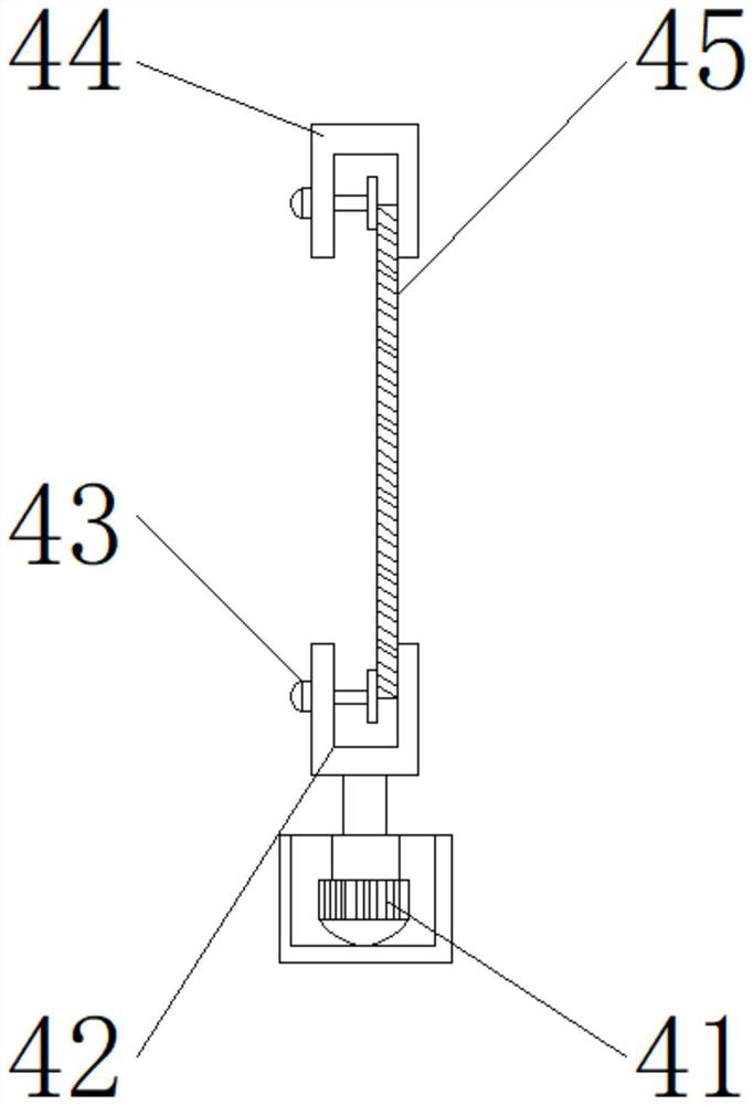
[0030] Such as Figure 1-5 As shown, the present invention provides a sandblasting device for wood products, comprising a main body 1, a sand storage box 2 is arranged at the lower end of the main body 1, a magnetic mounting block 3 is arranged at the lower end of the sand storage box 2, and a reducing Shock device 5, the outer surface of the front end of main body 1 is provided with direction adjusting device 6, one side of main body 1 is provided with auxiliary device 4, and the other side of main body 1 is provided with nozzle pipe 7; Holding mechanism 42, fixed bolt 43, concave module 44, slide bar 45, the clamping mechanism 42 is located at the upper end of the limit block 41, and the fixed bolt 43 is located at one side of the clamping mechanism 42; Between the fixed bolt 43 and the clamping mechanism 42 Thread grooves are provided, one side of the fixing bolt 43 is detachably connected to one side of the clamping mechanism 42 through the thread grooves, a welding block ...
Embodiment 2
[0033] Such as Figure 1-5 As shown, on the basis of Embodiment 1, the present invention provides a technical solution: preferably, the direction adjusting device 6 includes an adjusting rod 61, a pressing cap 62, a guide rod 63, a movable shaft 64, a movable wheel 65, and a movable shaft 64 Located on one side of the adjustment rod 61, the movable wheel 65 is located above the movable shaft 64, the pressing cap 62 is located at the upper end of the adjustment rod 61, and the guide rod 63 is located at the lower end side of the adjustment rod 61, and the adjustment rod 61 and the guide rod 63 are arranged There is a welding block, the lower end side of the adjustment rod 61 is fixedly connected with the lower end of the guide rod 63 through the welding block, an interface is arranged between the pressing cap 62 and the adjusting rod 61, and the upper end of the adjusting rod 61 is fixed with the lower end of the pressing cap 62 through the interface To connect, a threaded groo...
Embodiment 3
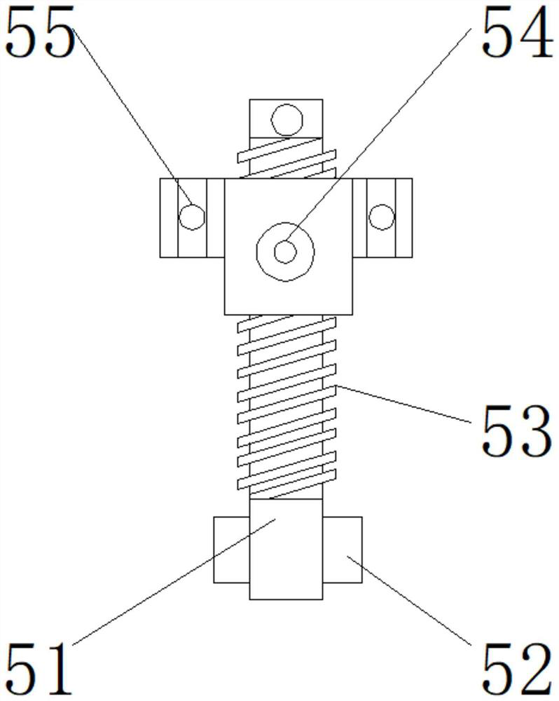
[0036] Such as Figure 1-5As shown, on the basis of Embodiment 1, the present invention provides a technical solution: preferably, the shock absorber 5 includes a spring seat 51, a bearing 52, a return spring 53, a shock absorber 54, a dust cover 55, and a return spring 53 is located at the upper end of the spring seat 51, the shock absorber 54 is located at the upper end of the return spring 53, the dust cover 55 is located at both sides of the shock absorber 54, the bearing 52 is located at the lower end of the spring seat 51, and the upper end of the spring seat 51 is reset through the interface. The lower end of the spring 53 is fixedly connected, a notch is provided between the bearing 52 and the spring seat 51, the upper end of the bearing 52 is detachably connected with the lower end of the spring seat 51 through the notch, and the shock absorber 54 and the dust cover 55 are provided with a Superglue, one side of the dust cover 55 is fixedly connected with both sides of...
PUM
 Abstract
Description
Claims
Application Information
 - R&D
- Intellectual Property
- Life Sciences
- Materials
- Tech Scout
- Unparalleled Data Quality
- Higher Quality Content
- 60% Fewer Hallucinations
Browse by: Latest US Patents, China's latest patents, Technical Efficacy Thesaurus, Application Domain, Technology Topic, Popular Technical Reports.
© 2025 PatSnap. All rights reserved.Legal|Privacy policy|Modern Slavery Act Transparency Statement|Sitemap|About US| Contact US: help@patsnap.com


