
Printing machine roller

A technology for printing machines and roller racks, applied in printing machines, rotary printing machines, printing, etc., can solve the problems of low work efficiency, slow manual cleaning speed, affecting production efficiency, etc., and achieve the effect of improving work efficiency

Active Publication Date: 2022-05-06
杭州名师文化传播有限公司
View PDF6 Cites 3 Cited by
  • Summary
  • Abstract
  • Description
  • Claims
  • Application Information

AI Technical Summary

Problems solved by technology

[0006] Aiming at the deficiencies of the prior art, the present invention provides a printing machine roller, which solves the problem that: in the existing market, the cleaning method for the glazing impurities in the micropores of the printing roller is usually to disassemble the printing roller after stopping the machine and manually clean it. The way of cleaning is to remove impurities. However, most of the printing work is continuous operation. Once the machine is shut down, it will greatly affect the production efficiency. At the same time, the manual cleaning speed is slow and the work efficiency is low;

Method used

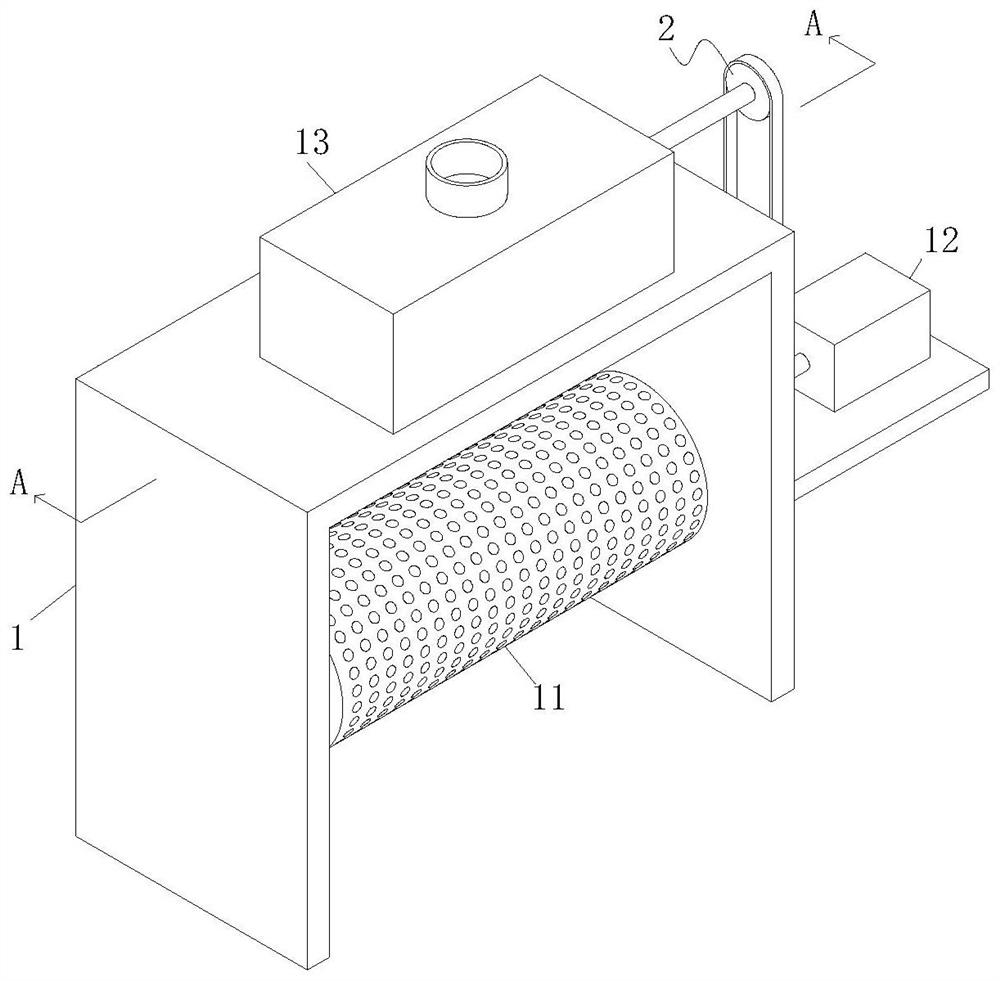
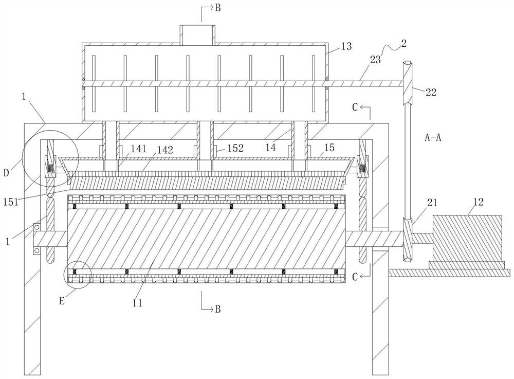
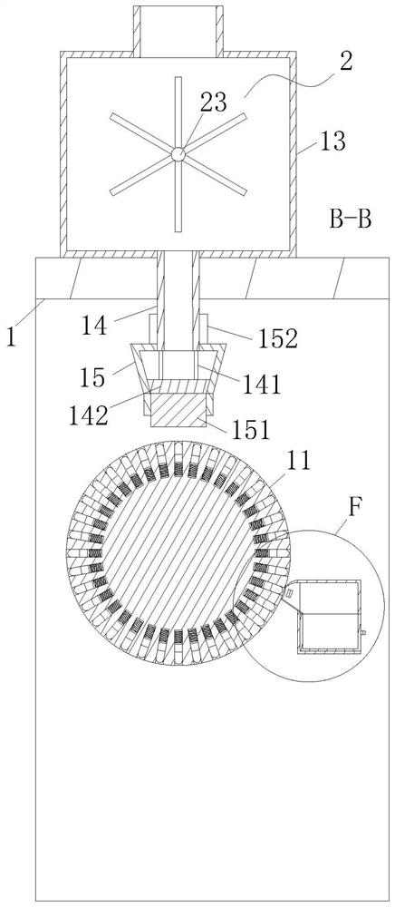

Image

  • Printing machine roller
  • Printing machine roller
  • Printing machine roller

Examples


Embodiment Construction

[0039] The following will clearly and completely describe the technical solutions in the embodiments of the present invention with reference to the accompanying drawings in the embodiments of the present invention. Obviously, the described embodiments are only some, not all, embodiments of the present invention. Based on the embodiments of the present invention, all other embodiments obtained by persons of ordinary skill in the art without making creative efforts belong to the protection scope of the present invention.

[0040] The embodiment of the present invention solves the cleaning method of the glazing impurities in the micropores of the printing roller in the prior art by providing a printing roller. Usually, the printing roller is disassembled and removed by manual cleaning after the machine is shut down. Miscellaneous, however, most of the printing work is a continuous operation, once the shutdown will greatly affect the production efficiency, and at the same time, the...


PUM


Abstract

The invention relates to the technical field of printing, in particular to a printing machine roller which comprises a roller frame, a roller is arranged on the front side in the roller frame, roller shafts on the left side and the right side of the roller are rotationally connected with a left side plate and a right side plate of the roller frame respectively, and the right side of the roller frame is fixedly connected with a motor through a rack. A roller shaft on the right side of the roller penetrates through a right side plate of the roller frame and is fixedly connected with an output shaft of the motor, and a cleaning mechanism is arranged on the rear side of the roller. The upper end face of the roller frame is fixedly connected with an ink box, and the lower end face of the ink box horizontally communicates with a plurality of ink conveying pipes at equal intervals. According to the printing machine roller, when the roller body rotates to the position of the collecting box, the magnet at the position of the feeding port of the collecting box can attract the punches in the micropores in the roller body, so that the punches eject impurities deposited in the micropores out of the micropores, and the impurities fall onto the material guiding plate under the scraping effect of the scraping plate and enter the material receiving groove along the material guiding plate; glazing caused by excessive accumulation of impurities in the micropores is avoided, meanwhile, cleaning can be carried out without shutdown, and the working efficiency is improved.

Description

technical field [0001] The invention relates to the technical field of printing, in particular to a printing machine roller. Background technique [0002] The printing efficiency of the roller printing machine is high, and it is widely used. The existing roller printing machine first dips one side of the printing roller into the ink when printing, and the ink will adhere to the outer peripheral surface of the printing roller. Rotate to print the ink onto the paper or fabric. In order to ensure the printing quality, the fabric will be pressed against the printing roller by a rigid pressure roller during printing. [0003] During the printing process of the existing printing roller, some residual impurities accumulate on the rubber surface of the printing roller, some of which can be cleaned with water or solvent, but a small amount of impurities still remain at the bottom of the micropores on the rubber surface. These residues accumulate in the holes for a long time. Under t...

Claims


Application Information

Patent Timeline
Patent Type & Authority Applications(China)
IPC IPC(8): B41F31/02B41F13/10B41F35/02B41F31/03
CPCB41F31/02B41F13/10B41F35/02B41F31/03Y02P70/10
Inventor 舒一苒赵宇琪
Owner 杭州名师文化传播有限公司
Learn More