

Printing machine roller
A technology for printing machines and printing rollers, applied in printing machines, rotary printing machines, printing, etc., can solve the problems of ink and dampening solution transfer performance deterioration, ink residue, printing difficulties, etc., to clean the surface of printing rollers, prevent Effects of glazing and improvement of printing performance
- Summary
- Abstract
- Description
- Claims
- Application Information
AI Technical Summary
Problems solved by technology
Method used
Image

Examples
Embodiment approach
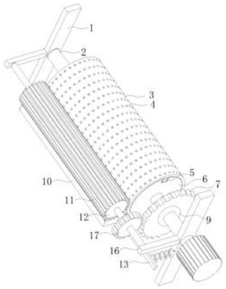
[0028] As a specific embodiment of the present invention, the main shaft 2 is connected to the rotating shaft 7 through gear meshing;
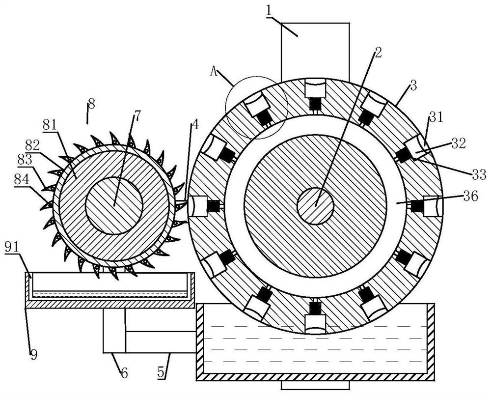
[0029] As the motor is energized, the main shaft 2 drives the printing roller 3 to rotate, and the main shaft 2 is connected to the rotating shaft 7 through gear meshing, so that the main shaft 2 can drive the rotating shaft to rotate at the same time, ensuring that the speed of the main shaft 2 and the rotating shaft 7 are consistent, so that the printing roller 3 and the cleaning roller 8 can cooperate with each other to achieve the purpose of cleaning the surface of the printing roller 2 and the residual ink in the micropore 31; at the same time, in order to ensure that the magnetic force generated by the electromagnetic rod 84 can have enough time to affect the metal piston 32, so the main shaft 2 And the rotating speed of rotating shaft 7 is 10-15r / min.
[0030] As a specific embodiment of the present invention, the printing roller 3 is p...
specific Embodiment approach
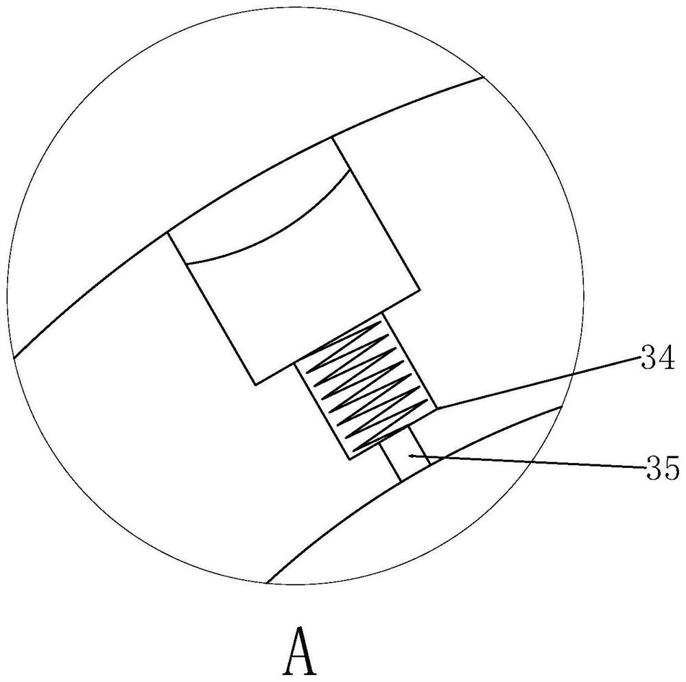
[0032] As a specific embodiment of the present invention, the metal piston 32 is in sliding and sealing connection with the inner wall of the micropore 31, and the top of the metal piston 32 is recessed inward to form a depression, and the high points on both sides of the depression of the metal piston 32 are separated from the micropore. At 2-3mm at the mouth of 31, the maximum distance between the metal piston 32 and the surface of the printing roller 3 is that the lowest point of the metal piston 32's concave surface exceeds the mouth of the micropore 31 by 1-2mm;
[0033] When the surface of the printing roller 3 dipped in ink rotates to a position away from the top working surface, after the dyeing process is finished, part of the residual ink remains in the micropore 31, and the metal piston 32 cooperates with the inner wall of the micropore 31 without clearance to ensure that the inside of the micropore 31 At the same time, the residual ink in the micropore 31 accumulate...
PUM
 Abstract
Description
Claims
Application Information