

Driving circuit
A drive circuit, drive control technology, applied in the direction of logic circuit, logic circuit interface device, logic circuit connection/interface layout, etc., can solve the problem of inaccurate current limiting
- Summary
- Abstract
- Description
- Claims
- Application Information
AI Technical Summary
Problems solved by technology
Method used
Image

Examples
Embodiment Construction
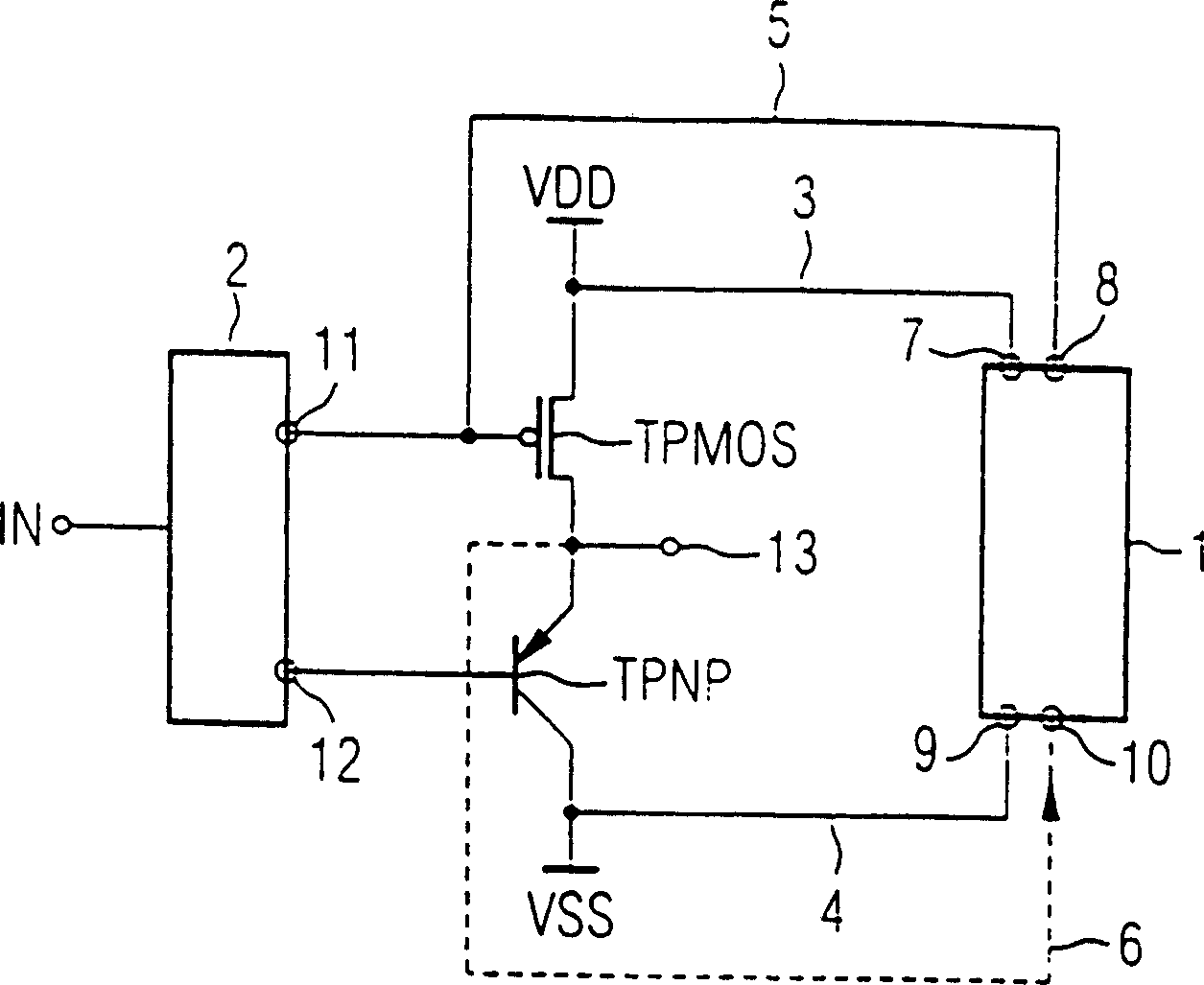
[0023] Such as figure 1 As shown, the drive control part 2 has an input terminal IN and a first output terminal 11 and a second output terminal 12 . The first output terminal 11 is connected to the p-channel-MOS-drive transistor TPMOS. The second output 12 is connected to the control port of the pnp bipolar driver transistor TPNP. The load line segment of the first driving transistor TPMOS is connected between the first power supply voltage VDD and the output terminal 13 of the driving circuit. The load line segment of the second driving transistor TPNP is connected between the second power supply voltage VSS and the output terminal 13 of the driving circuit. The two drive transistors can be implemented in MOS technology or in bipolar technology. Generally, in a digital circuit, the first power supply voltage VDD is 5V and the second power supply voltage VSS is 0V, but other power supply voltages can also be selected, for example, the first power supply voltage 3.3V is sele...
PUM
 Abstract
Description
Claims
Application Information