[0039] Attached to the following Figure 1-8 This application will be described in further detail.
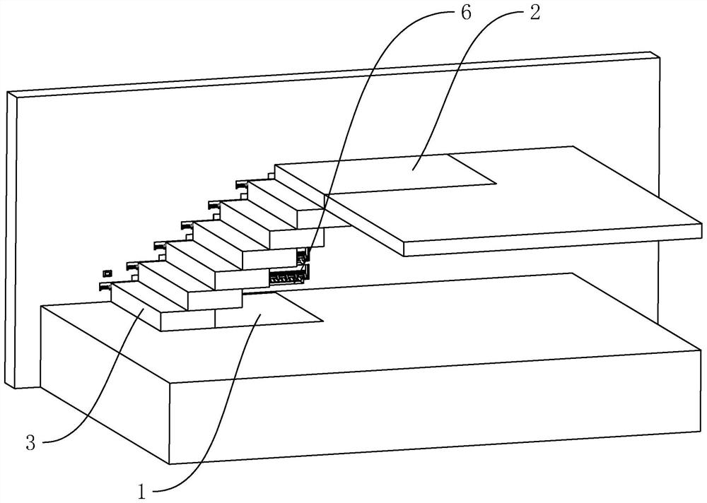
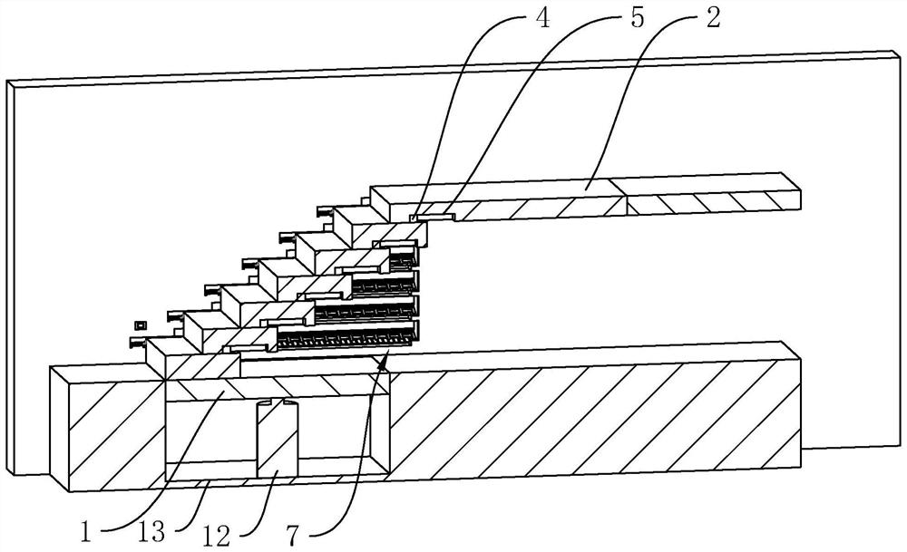
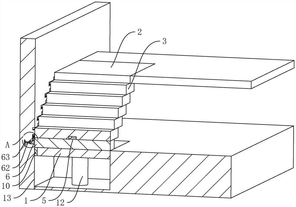
[0040] The embodiment of the present application discloses an adjustable staircase. refer to figure 1 and figure 2 , the adjustable staircase includes a first platform 1, a second platform 2 and a plurality of floor plates 3 located on the ground, the second platform 2 is located above the first platform 1, and a plurality of floor plates 3 are stacked in a stepped shape for connecting the first platform 1 and the For the second platform 2 , the first platform 1 is located at the bottom of several floor slabs 3 , and the second platform 2 is located on the top of several floor slabs 3 . The floor 3 is slidably connected to the wall, the top of the floor 3 is cast and fixed with a limit block 4, the bottom of the floor 3 is provided with a limit slot 5, and the limit block 4 of the adjacent floor 3 is adapted to be inserted into the limit slot 5, and The length of the limit slot 5 is equal to the moving length of the limit block 4 . An accommodating groove 13 is opened on the ground, the first platform 1 is adapted to be accommodated in the accommodating groove 13, and the upper surface of the first platform 1 is flush with the ground, and a lifting driving member 12 is placed in the accommodating groove 13. This embodiment In an example, the lift driving member 12 adopts an air cylinder, the output end of the lifting driving member 12 is glued and fixed to the side of the first platform 1 away from the floor 3 , and the lifting driving member 12 drives the first platform 1 to move in the vertical direction.
[0041] When the goods need to be transported upstairs, push the floor slab 3 so that the limit block 4 abuts the inner side wall of the limit slot 5, and restricts the adjacent floor slabs 3 to continue staggered movement, so that several floor slabs 3 are stacked neatly, and several floor slabs 3 are in the second In the vertical downward area of the platform 2, place the article on the first platform 1, activate the lift drive 12, so that the first platform 1 moves away from the ground until the first platform 1 and the second platform 2 are aligned At this time, the first platform 1 and the second platform 2 are located in the same plane, and the article is pushed from the first platform 1 to the second platform 2 to complete the transportation of the article. When the floor 3 needs to be unfolded, start the Lift the driving member 12, drive the first platform 1 to move toward the ground, until it is completely accommodated in the accommodating slot 13, and pull the floor 3 close to the ground, the limit block 4 and the inner side of the limit slot 5 of the previous floor 3 The walls are in contact with each other, driving the previous floor slab 3 to move, and abutting in turn, all the floor slabs 3 can be unfolded, and the operation is convenient.
[0042] refer to image 3 and Figure 4 , the side walls and the walls of several floors 3 are slidably connected to the walls through a sliding mechanism 7. The sliding mechanism 7 includes a sliding block 71. The side of the wall close to the floor 3 is provided with a sliding groove 6, and the sliding block 71 is adapted to be inserted into the wall. In the chute 6 , the length of the chute 6 is equal to the moving distance of the floor 3 .
[0043] refer to Figure 4 and Figure 5 , the side of the slider 71 away from the floor 3 is cast and fixed with the guide rod 14, the side of the chute 6 away from the floor 3 is provided with a guide groove 62, and the guide rod 14 is adapted to be inserted into the guide groove 62. The length of the guide groove 62 The length of the guide rod 14 is equal to the length of the chute 6. A baffle 141 is cast and fixed at one end of the guide rod 14 away from the slider 71. The baffle 141 is perpendicular to the guide rod 14. The inner wall of the guide groove 62 has a positioning groove 63 along the length direction. Inserted into the positioning groove 63 . When the slider 71 slides in the chute 6, the guide rod 14 slides in the guide groove 62, and the guide rod 14 abuts against the inner wall of the guide groove 62 to play a guiding role, so that the floor 3 moves along the length direction of the guide groove 62, Offset is not easy to occur, and the baffle 141 acts as a block, which increases the stability of the floor 3 on the wall, makes the floor 3 difficult to separate from the wall, and increases the safety of people walking on the floor 3 .
[0044] refer to image 3 , a buffer pad 10 is glued and fixed on the side of the first platform 1 close to the wall, and the buffer pad 10 is in contact with the side of the wall close to the floor 3 . The chute 6 makes the side of the wall close to the floor 3 uneven, and the buffer pad 10 is made of rubber. When the first platform 1 moves on the side wall of the wall body, the buffer pad 10 abuts against the side wall of the wall body, so that the chute 6 is not easy to Interference with the movement of the first platform 1 .
[0045] refer to Image 6 and Figure 7 , the sliding mechanism 7 also includes abutting springs 72, abutting plates 73, several abutting blocks 74 and connecting rods 75. Several abutting blocks 74 are evenly distributed along the length direction of the abutting plate 73, and the abutting blocks 74 are in contact with the The plates 73 are rotatably connected by a rotating shaft. The sliding block 71 is located between the adjacent abutting blocks, and the sliding block 71 is in contact with the side wall of the abutting block 74. The side of the sliding groove 6 away from the ground is provided with an abutting groove 61. , the abutment plate 73 is placed in the abutment groove 61, one end of the abutment spring 72 is glued and fixed with the side of the abutment groove 61 away from the ground, and the other end is glued and fixed with the abutment plate 73, which is used for the abutment plate 73 is pushed in the direction close to the ground, the connecting rod 75 is passed through the abutting block 74 and is rotatably connected with the abutting block 74, the connecting rod 75 is slidably connected with the wall, and one end of the connecting rod 75 is integrally formed with a support rod 8, and the support rod 8 Perpendicular to the connecting rod 75, the side of the wall close to the floor 3 is provided with a sliding groove 9, the sliding groove 9 is communicated with the abutting groove 61, the support rod 8 passes through the sliding groove 9 and extends out of the wall, and the wall is close to the floor. One side of 3 is provided with a first installation slot 91 and a second installation slot 92, the first installation slot 91 and the second installation slot 92 are both connected with the sliding slot 9, and the first installation slot 91 is provided in the second installation slot 92 away from On one side of the abutting block 74, the inner diameter of the first installation groove 91 and the second installation groove 92 is equal to the outer diameter of the support rod 8, and the side of the wall close to the floor 3 is provided with an adjustment hole 93. The first installation groove 91 and the first installation groove The two installation slots 92 are both communicated with the adjustment holes 93 . The iron sheet 11 is glued and fixed on the side of the first installation slot 91 and the second installation slot 92 away from the ground, and the side wall of the support rod 8 is glued and fixed with a magnet 81 , and the magnet 81 is attached to the iron sheet 11 for supporting The rod 8 is fixed on the wall.
[0046] When the floor 3 needs to be retracted, force is applied to the support rod 8, move the support rod 8 in the direction close to the abutment block 74, rotate the support rod 8, and place the support rod 8 in the second installation groove 92, so that the abutment The block 74 is inclined in the direction away from the support rod 8, and the side wall of the support rod 8 is in contact with the inner wall of the second installation groove 92, so that the inclination angle of the abutting block 74 is fixed. 8. It is not easy to flip out the second installation groove 92, push the floor plate 3, the floor plate 3 moves in the direction away from the support rod 8, the side wall of the slider 71 abuts against the abutment block 74, and the abutment block 74 is inclined to play a guiding role, compressing the abutting block 74. The spring 72 is connected to press the abutting block 74 away from the ground, and the magnet 81 and the iron piece 11 slide until the abutting block 74 is completely accommodated in the abutting groove 61, so that the abutting block 74 does not touch the slider. The movement of 71 causes interference. When the side wall of the slider 71 abuts against the inner wall of the chute 6 away from the support rod 8, the abutment spring 72 restores its deformation and pushes the abutment block 74 toward the ground, so that the abutment The block 74 is in abutment with the slider 71 and plays a restricting role, so that the slider 71 is not easy to move in the direction close to the support rod 8 , thereby fixing the floor plate 3 on the wall.
[0047] When several floor slabs 3 need to be unfolded into stairs, hand into the adjustment hole 93 to separate the magnet 81 from the iron sheet 11, so that the support rod 8 is turned out of the second installation slot 92, and the support rod 8 is moved away from the abutment block 74. Move the support rod 8 in the first installation slot 91, so that the abutment block 74 is inclined in the direction close to the support rod 8, so that the slider 71 can move in the direction close to the support rod 8, when the limit block 4 After both are in contact with the side of the limiting groove 5 close to the support rod 8, the abutment block 74 is in contact with the slider 71, so that the slider 71 is not easy to move away from the support rod 8, so that several floor slabs 3 are stacked in a staggered state. be fixed.
[0048] refer to Figure 8 , the slider 71 close to the first platform 1 is connected with a moving mechanism 15, and the moving mechanism 15 is used to drive the floor 3 to slide on the first platform 1 and the ground. The moving mechanism 15 includes a moving rod 151 and a moving driving member 152. In the embodiment of the present application, the moving driving member 152 adopts a servo motor. The output end is connected with one end of the moving rod 151, and the moving driving member 152 is used to drive the moving rod 151 to rotate. When the floor 3 needs to be moved, the moving driving member 152 is activated, so that the moving rod 151 rotates, so that the sliding block 71 moves, so that the sliding block 71 close to the first platform 1 slides in the chute 6 and drives the sliding block 71 close to the first platform. When the floor plates 3 of 1 move, when the limit blocks 4 are in contact with the inner wall of the limit groove 5 in sequence, all the floor plates 3 can be driven to move, which is convenient to operate and saves time and effort.
[0049] The implementation principle of an adjustable staircase in the embodiment of the present application is as follows: when the article needs to be transported upstairs, the moving driving member 152 is activated, so that the moving rod 151 rotates, so that the sliding block 71 moves, and the limit block 4 is connected to the upper block. The inner side walls of the limit grooves 5 of the floor 3 are in contact with each other, which drives the previous floor 3 to move, and abuts in turn to realize the movement of all the floors 3. When the limit block 4 on the floor 3 of the second platform 2 is close to the limit groove 5. The inner walls are in contact with each other, stop moving the driving member 152, so that several floor slabs 3 are stacked neatly, and several floor slabs 3 are in the area where the second platform 2 is vertically downward. Place the article on the first platform 1, and start the lifting and lowering driving member 12. , so that the first platform 1 is moved away from the ground until the first platform 1 and the second platform 2 are flush. 1 is pushed up to the second platform 2 to complete the transportation of the articles. When the floor 3 needs to be unfolded, the lifting and lowering drive member 12 is activated to drive the first platform 1 to move towards the direction close to the ground until it is completely accommodated in the accommodating slot 13 In the middle, the moving driving member 152 is activated to realize the reversal of the moving rod 151, and the limit block 4 is in contact with the inner wall of the opposite side of the limit slot 5, thereby driving all the floors 3 to move, realizing the unfolding of the floors 3, and the operation is convenient.
[0050] The above are all preferred embodiments of the present application, and are not intended to limit the protection scope of the present application. Therefore: all equivalent changes made according to the structure, shape and principle of the present application should be included in the protection scope of the present application. Inside.