Pathological section device capable of realizing double-sided section

A technology of pathological section and sectioning device, applied in the field of pathological section, can solve the problems of affecting section quality, large deviation of section thickness, fracture of pathological section, etc., and achieve the effect of improving sectioning efficiency, improving sectioning precision, and improving accuracy.

Inactive Publication Date: 2022-05-06
郑州大学第三附属医院
0 Cites 0 Cited by

AI-Extracted Technical Summary

Problems solved by technology

However, most of the existing pathological slicing devices are unidirectional slices. Due to the thin slice thickness, the slice volume of a group of prepared pathological samples is relatively large. Therefore, the effect of unidirectional slicing is low, and during the slicing process, the The deviation of slice thickness is larg...

Method used

Transmission assembly two 65, multiple groups are arranged equidistantly before and after, and embedded in the cutting blade inside above the top of the outer inclined blade, and its right side is on the same plane as the right side of the cutting blade, conveying The second component is a free transmission structure, that is, there is no power drive, and the conveyor belt can be forced to run by itself to improve...

Abstract

The invention discloses a pathological section device capable of slicing on two sides. The pathological section device comprises a fixed box frame; the transverse moving devices are installed at the top and the bottom of the fixed box frame and are arranged in two sets in a front-back parallel mode, slicing devices arranged in a left-right symmetry mode are installed on the transverse moving devices on the front side and the rear side of the upper portion in a matched mode, and collecting devices arranged in a left-right symmetry mode are installed on the transverse moving devices on the front side and the rear side of the lower portion in a matched mode; and the two groups of load battens are arranged front and back, are positioned in the middle of the left and right slicing devices, and are fixed on the front and back side plate walls close to the bottom of the fixed box frame.

Application Domain

Technology Topic

Image

  • Pathological section device capable of realizing double-sided section
  • Pathological section device capable of realizing double-sided section
  • Pathological section device capable of realizing double-sided section

Examples

  • Experimental program(1)

Example Embodiment

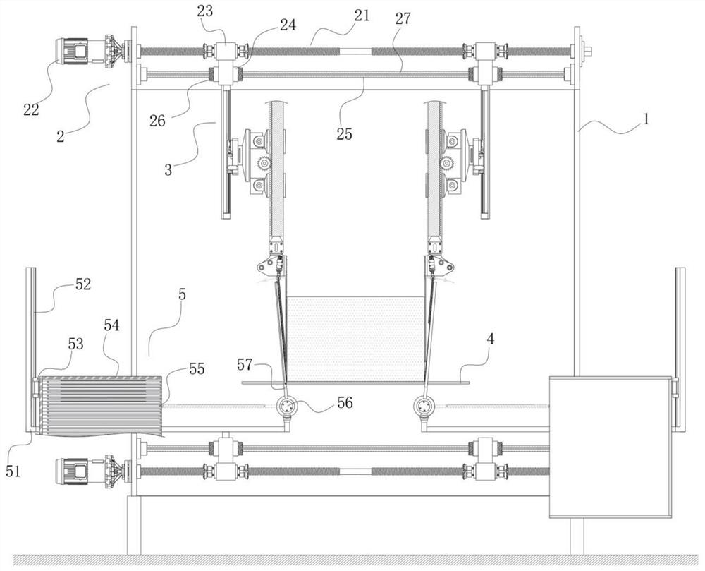
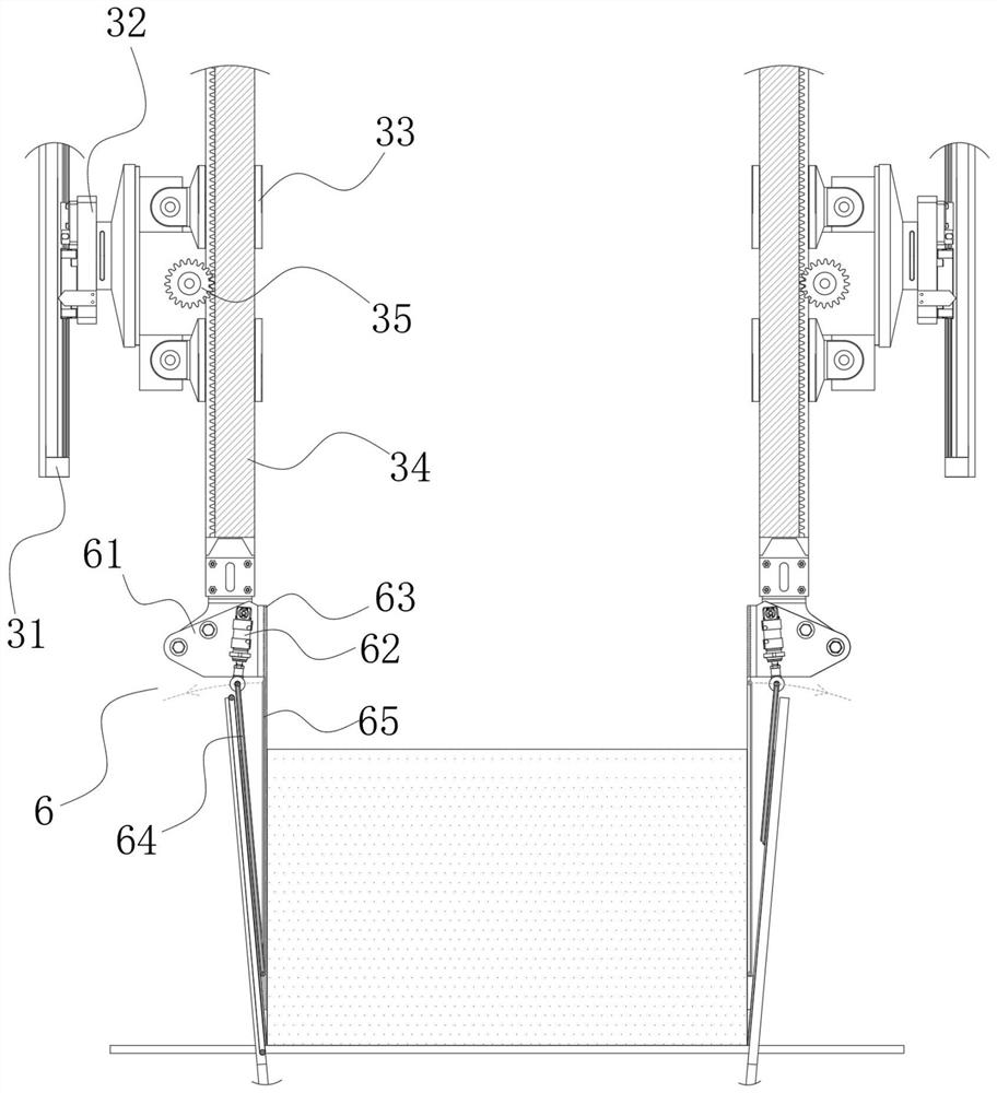
[0039] refer to Figure 1-4 , the present invention provides a technical solution: a pathological slicing device capable of double-sided slicing, which comprises:
[0040] Fixed box frame 1;
[0041] The traverse device 2 is installed on the top and bottom of the fixed box frame 1, and two groups are arranged in parallel in the front and rear, and the slicing device 3 is arranged symmetrically on the front and rear sides of the upper and lower sides. The traverse device 2 on the front and rear sides is equipped with a collecting device 5 which is symmetrically arranged on the left and right;
[0042] Loading strips 4 are arranged in two groups at the front and rear, located in the middle of the slicing device 3 on the left and right sides, and fixed on the front and rear side walls of the fixed box frame 1 near the bottom, for placing pathological samples.
[0043] In this embodiment, a group of the traverse devices 2 includes:
[0044] The left and right ends of the screw 21 are respectively fixed with the output end of the motor 22 fixed on the left box frame of the fixed box frame 1. The right box frame of the fixed box frame 1 is rotatably connected, and is located at the left half rod and the right half of the screw rod 21. The rotation directions of the threads provided on the outside of the rod are oppositely rotated;
[0045] The screw sleeves 23 are configured into two groups, which are arranged symmetrically on the left and right sides and are sleeved on the left and right sides of the screw 21 for external engagement of the threads;
[0046] The auxiliary sliding rod 25 is arranged in parallel with the screw rod 21, and its left and right ends are fixed on the left and right box frames of the fixed box frame 1;
[0047] The limiting slide cylinders 24 are configured into two groups, which are both sleeved on the auxiliary bearing slide rods 25 and slidably connected, and are both fixed to the screw sleeves 23 through the connecting plate collar.
[0048] In this embodiment, an axial fluorescent body is provided inside the auxiliary sliding rod 25, and a fluorescent scale 27 is provided on the outer rod wall. The fluorescent body in the supporting slide rod scatters parallel light to the outside.
[0049] In this embodiment, the annular end of the screw sleeve 23 is equipped with a light sensing monitoring ring 26 for monitoring and reading the scale value of the fluorescent scale 27. During the movement process, the number of scales on the light-shielding scale of the fluorescent scale is calculated, thereby greatly improving the degree of The accuracy of the slice is improved, thereby improving the consistency rate between the thickness of the pathological slice and the thickness of the actual required value.
[0050] In this embodiment, the slicing device 3 includes:
[0051] The guide rail one 31 is arranged in two groups in parallel at the front and rear, and the upper ends of the guide rails are respectively fixed with the limit sliding cylinders 24 on the front and rear sides;
[0052] The driving seat 1 32 is correspondingly installed on the guide rail 1 31, and a fixed sliding cylinder 33 arranged in parallel and coaxially up and down is installed on the right seat plate. The drive gear 35 on the right side seat plate of the drive seat, and the longitudinally penetrating cavity inside the fixed sliding cylinder 33 is a square cavity. , and then perform the torsion limit on it;
[0053]The rack bar 34 is in the form of a square prism, and the left side plate is provided with a rack embedded in the plate, which is meshed and connected with the driving gear 35, and the lower ends of the rack bars 34 on the front and rear sides are fitted with slices. Component 6.
[0054] In this embodiment, the slicing component 6 includes:
[0055] The fixing bases 61 are configured into two groups, which are respectively installed on the lower ends of the rack bars 34 on the front and rear sides, respectively, and are hinged on the side seat plates facing the inclination angle adjusting rods 62 that are symmetrically arranged in the front and rear;
[0056] The left side of the upper end of the cutting blade 63 is fixed with the right side of the fixing seat 61 on the front and rear sides, and the cutting blade 63 is provided with an outer inclined blade with a partial angle of 5°;
[0057] A transmission assembly 64, the upper end of which is hingedly connected to the inclination adjustment rod 62, and the lower end of which is hinged to the outer side of the cutting blade at the top of the outer inclined blade;
[0058] The second transmission assembly 65 is arranged in multiple groups at equal distances in the front and rear, and is embedded in the cutting blade above the top of the outer inclined blade, and its right side is in the same plane as the right side of the cutting blade. The second transmission assembly is: Free transmission structure, that is, without power drive, the conveyor belt can be forced to run by itself, improving the coincidence of its right side and the pathological slice side;
[0059] Among them, according to the solid strength, flexibility and slice thickness of the pathological slice, the value of the maximum bending degree that the slice can withstand is selected, and the transmission component 1 is adjusted by the inclination adjustment rod. make corresponding adjustments;
[0060] As a preferred embodiment, the transmission component 1 can be selected from a range of 5° to 20°. Outside this range, further precise selection can be performed according to the structure of the actual pathological slice sample.
[0061] In this embodiment, the transmission component one 64 includes:
[0062] The upper and lower ends of the swing rod 641 are hingedly connected with the output end of the inclination adjustment rod 62 and the cutting blade at the bottom end of the outer inclined blade;
[0063] The drive shaft 642 is installed corresponding to the upper and lower ends of the pendulum rod 641, and the outside of the drive shaft 642 is covered with rotating wheels arranged in a front and rear equidistant arrangement, and the outer sides of each set of rotating wheels on the same plane are covered with a conveyor belt 643;
[0064] Among them, the conveyor belts are arranged side by side at intervals, while ensuring the transmission of pathological slices, reducing the local large-area contact and enhancing the detachment strength of the pathological slices, so that when the pathological slices are cut with the cutting blade, they lean on the conveying assembly 41 volumes.
[0065] In this embodiment, the collection device 5 includes:
[0066] The fixed plate frame 51 is arranged in two groups in parallel at the front and rear, and is fixed on the limit slider located below the front and rear sides, and the left longitudinal plate frame is installed with a guide rail 52, and its right end is installed with a rotating wheel 56 , and a second drive seat 53 is installed on the second guide rail 52;
[0067] The left side of the collection box 54 is fixed with the second drive seat 53, and the third transmission assembly 55 arranged in a longitudinally equidistant arrangement is installed inside the collection box 54;
[0068] The lower end of the auxiliary support plate 57 is installed on the rotating wheel 56 , and the transmission assembly 4 is embedded and installed on the right side plate.
[0069] In specific implementation, it includes the following steps:
[0070] S1: Place the pathological sample on the load slat, start the drive seat, adjust the lower end of the cutting blade and the upper surface of the load slat to be close to the upper surface of the load slat, and then start all the synchronously arranged motors in the traverse device to make the cutting blade approach the inner side, At the same time, the pathological sample is attached and moved, so that the left and right cutting blades are in contact with the left and right sides of the pathological sample;
[0071] S2: Start the light-sensing monitoring ring to automatically monitor the distance, that is, whether the left and right light-sensing monitoring rings move from the beginning to the end in the process of S1 is the same. If so, the left and right screw sleeves are in a normal state. Go to S3, if not, overhaul the traverse device and go to S1 again;
[0072] S3: According to the solid strength and flexibility of the pathological sample, select the appropriate tilt angle of the first transmission component, wherein the tilt angle adjustment rod is used for hinged joint, and the slice thickness value is preset, that is, after each slice is completed, the , the screw sleeve is driven by the motor to urge the cutting blade to approach inward, and the thickness value of the slice can be automatically changed again halfway;
[0073] S4: The value obtained by multiplying the moving speed of the conveyor belt driven by the drive shaft in the first transmission assembly by cosA, the moving speed of the driving shaft in the fourth conveying assembly is also cosA, which is consistent with the moving speed of the driving seat 1, so that the cutting blade moves down When the cut pathological section and the conveyor belt are in a relatively static state, A is the angle between the conveyor assembly 1 and the longitudinal plane. The drive shaft in component 4 rotates counterclockwise. On the contrary, the transmission component 2 is a free transmission structure, that is, there is no power drive, and the conveyor belt can be forced to run by itself;
[0074] S5: After a set of pathological slices is completed, the auxiliary support plate is externally rotated to the horizontal level by the rotating wheel, and is three-phase flush with a group of transmission components, and the pathological slices are transmitted to the transmission component 3 through the transmission component 4 for collection, and then Driven by the driving seat 2 to move up, causing the next group of empty conveying assemblies 3 to move up, waiting for the introduction of the next group of pathological slices.
[0075] The above description is only a preferred embodiment of the invention, but the protection scope of the present invention is not limited to this. Equivalent replacements or changes to the inventive concept shall all fall within the protection scope of the present invention.

PUM

no PUM

Description & Claims & Application Information

We can also present the details of the Description, Claims and Application information to help users get a comprehensive understanding of the technical details of the patent, such as background art, summary of invention, brief description of drawings, description of embodiments, and other original content. On the other hand, users can also determine the specific scope of protection of the technology through the list of claims; as well as understand the changes in the life cycle of the technology with the presentation of the patent timeline. Login to view more.

Similar technology patents

Method and device for forecasting reservoir yield

InactiveCN101906966AHigh precisionSurveyWellheadVolume factor
Owner:PETROCHINA CO LTD

Classification and recommendation of technical efficacy words

Why Eureka
Try Eureka