

Wiring terminal automatic processing device and processing method thereof
A terminal block and processing device technology, which is applied in the field of automatic processing devices for terminal blocks, can solve the problems of affecting the processing efficiency of terminal blocks and reducing the efficiency of terminal blocks, and achieves the effects of reducing labor costs, reducing labor force, and avoiding multiple placements
- Summary
- Abstract
- Description
- Claims
- Application Information
AI Technical Summary
Problems solved by technology
Method used
Image

Examples
Embodiment approach
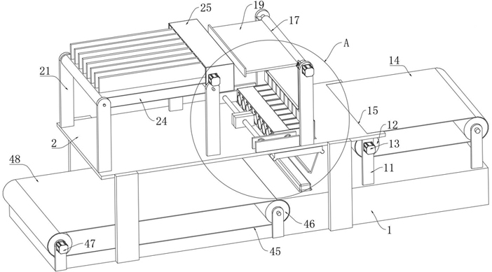
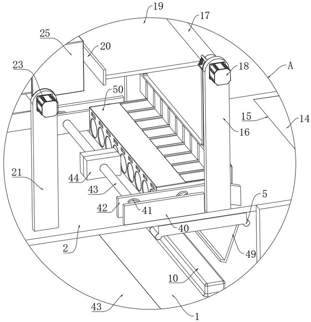
[0050] As an embodiment of the present invention, the feeding device includes a second rotating shaft 17 and a second motor 18, the second rotating shaft 17 is rotatably installed between two second mounting brackets 16, and the second motor 18 is fixed to one of them by screws. On the side wall of the second mounting frame 16, the output shaft of the second motor 18 passes through the second mounting frame 16 and is fixedly connected with the second rotating shaft 17. A magnetic suction transfer mechanism is installed on the side wall of the second rotating shaft 17, and the magnetic suction transfer The mechanism is used to convey the copper sheet, and the copper sheet is placed inside the terminal housing 50 through magnetic attraction, and a pressing mechanism is installed on the side wall of the second rotating shaft 17, and the pressing mechanism is used to carry out the placed wiring terminal. Compression assembly, the feeding device and the compression mechanism coopera...
PUM
 Abstract
Description
Claims
Application Information