Automatic stepless variable power speed regulation motor and speed regulation method thereof

A speed-regulating motor, stepless technology, applied in the direction of a single motor speed/torque control, electromechanical devices, electrical components, etc., can solve the problems of unsatisfactory speed regulation effect and difficulty in magnetic regulation of permanent magnet synchronous motor. The effect of moving difficulty and reducing volume

Pending Publication Date: 2022-05-06
ZHONGCI POWER EQUIP (SHENZHEN) CO LTD
View PDF0 Cites 0 Cited by
  • Summary
  • Abstract
  • Description
  • Claims
  • Application Information

AI Technical Summary

Problems solved by technology

[0006] The purpose of the present invention is to provide an automatic stepless power variable speed regulating motor and its speed regulating method, so as to solve the problems of difficult magnetic field regulation and unsatisfactory speed regulating effect of permanent magnet synchronous motors in the prior art, and realize the axial The magnetic flux is radially separated from the magnetic field to broaden the variable power and speed regulation range of the permanent magnet synchronous motor and improve the operating efficiency of the high-speed area system.

Method used


Image

  • Automatic stepless variable power speed regulation motor and speed regulation method thereof
  • Automatic stepless variable power speed regulation motor and speed regulation method thereof
  • Automatic stepless variable power speed regulation motor and speed regulation method thereof

Examples


Embodiment 1

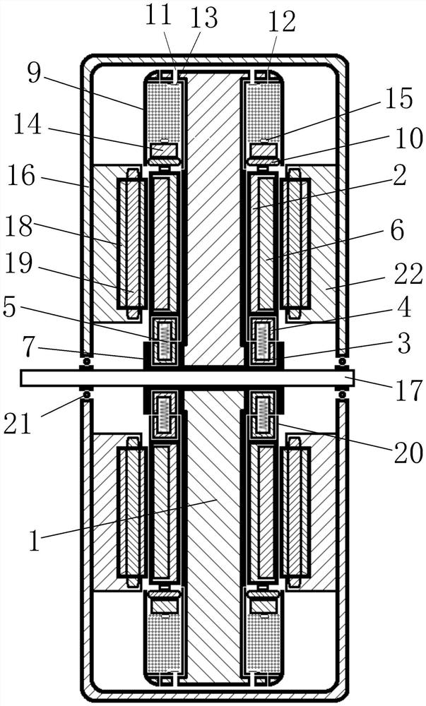
[0044] Such as figure 1 The shown automatic stepless power variable speed regulating motor includes a casing 16, a stator assembly and a rotor assembly located in the casing 16, and a main shaft 17 connected to the rotor assembly; the stator assembly includes a stator core 18 . The stator coil 19, the rotor assembly includes a rotor 1, a rotor core 2, and a rotor magnet 6;

[0045] The stator assembly and the rotor assembly are axially distributed along the main shaft 17;

[0046] The rotor core 2 is slidably fitted on the end face of the rotor 1 facing the direction of the stator assembly along the radial direction;

[0047] It also includes a radial clutch device arranged at the inner diameter end of the rotor core 2, and an air damping centrifugal device arranged at the outer diameter end of the rotor iron core 2; the radial clutch device is used to control the separation and engagement of the rotor iron core 2 in the radial direction, The air damping centrifugal device i...

Embodiment 2

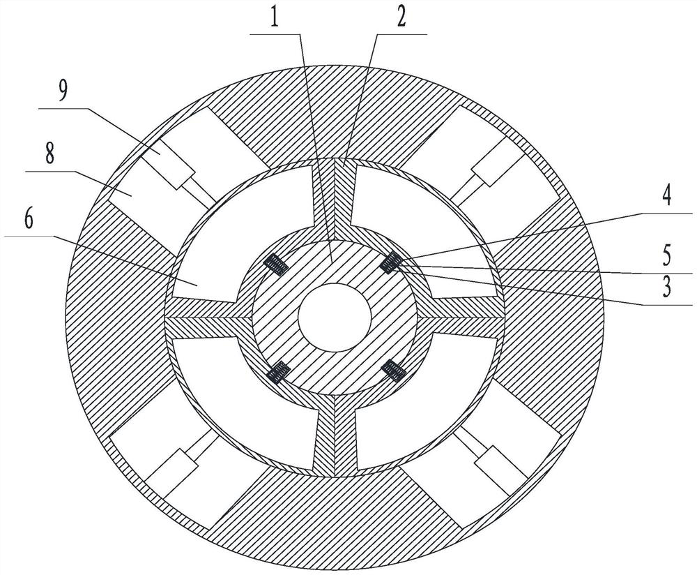
[0057] An automatic stepless power variable speed regulating motor. On the basis of Embodiment 1, the radial clutch device includes a first magnetic part 3 and a second magnetic part 4 distributed along the sliding direction of the rotor core 2. The first magnetic part A magnetic part 3 is relatively fixed to the rotor 1, the second magnetic part 4 is relatively fixed to the rotor core 2, and the first magnetic part 3 and the second magnetic part 4 are magnetically attracted; 3 and the elastic part 5 between the second magnetic part 4. Wherein the first magnetic part 3 is located on the radially inward side of the second magnetic part 4 .

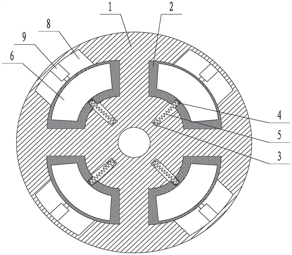
[0058] This embodiment is in stationary state or low-speed rotation as figure 2 Shown; when the rotor rotates at high speed, such as image 3 As shown, the rotor core moves radially outward under the action of centrifugal force, which weakens the magnetic field strength between the rotor magnet and the stator core, and realizes the funct...

Embodiment 3

[0066] An automatic stepless power variable speed regulating motor. On the basis of any of the above embodiments, the air damping centrifugal device includes a rotor 1, a rotor core 2 matching the rotor 1, and the rotor core 2 Slidingly fit on the end surface of the rotor 1 in the radial direction; it also includes a damping cylinder 9 arranged on the end surface of the rotor 1 and located radially outside the rotor core 2, and a piston 10 located in the damping cylinder 9, the piston 10 and the rotor iron The core 2 is fixedly connected, and an air inlet 11 and an air outlet 12 are provided on the damping cylinder 9 . A one-way valve 13 is provided at the air inlet 11 , and the one-way valve 13 leads toward the direction of entering the inside of the damping cylinder 9 .

[0067] Such as figure 1 As shown, this embodiment also includes a counterweight 14 fixedly connected with the piston 10 . The counterweight 14 is fixed on the radially outer side of the piston 10 . It al...


PUM


Abstract

The invention discloses an automatic stepless variable power speed regulation motor and a speed regulation method thereof. The automatic stepless variable power speed regulation motor comprises a shell, a stator assembly, a rotor assembly and a main shaft, the stator assembly and the rotor assembly are axially distributed along the main shaft; the rotor iron core is in sliding fit with the end face, facing the stator assembly, of the rotor in the radial direction; the radial clutch device is arranged at the inner diameter end of the rotor core; the air damping centrifugal device is arranged at the outer diameter end of the rotor core; the radial clutch device is used for controlling separation and connection of the rotor iron core in the radial direction, and the air damping centrifugal device is used for providing damping when the rotor iron core slides outwards in the radial direction; when the radial clutch device is connected, the rotor iron core and the stator iron core are axially opposite to each other. The permanent magnet synchronous motor is used for solving the problems that in the prior art, a permanent magnet synchronous motor is large in magnetic adjusting difficulty, not ideal in speed adjusting effect and the like, and the purposes of widening the variable power speed adjusting range of the permanent magnet synchronous motor and improving the operation efficiency of a high-speed area system are achieved by conducting radial separation magnetic adjusting on axial magnetic flux.

Description

technical field [0001] The invention relates to the field of permanent magnet synchronous motors, in particular to an automatic stepless power variable speed regulating motor and a speed regulating method thereof. Background technique [0002] With the rapid development of science and technology and the continuous deepening of research, especially the arrival of the information digital age, there is an urgent need for electric drive systems to develop in the direction of high power, high efficiency, wide speed range, high torque, and high performance volume ratio. From the perspective of international scientific and technological development trends, high-efficiency and energy-saving variable frequency drives are an important development direction in major areas of the national economy such as industrial control, household appliances, and transportation. [0003] With the improvement of frequency conversion technology, permanent magnet synchronous motor and frequency conversi...

Claims


Application Information

Patent Timeline
Patent Type & Authority Applications(China)
IPC IPC(8): H02K7/10H02K7/12H02K7/04H02K1/2796H02K1/30H02P6/08
CPCH02K7/10H02K7/12H02K7/04H02K1/2793H02K1/30H02P6/08
Inventor 钱凤军罗业富何刚
Owner ZHONGCI POWER EQUIP (SHENZHEN) CO LTD
Why Eureka
Try Eureka