

Drip infusion device capable of automatically stopping
An infusion device and automatic stop technology, which is applied in other medical devices, hypodermic injection devices, flow monitors, etc., can solve the problems of unsuitable hanging bottles, pollution, etc., and achieve convenient hemostasis operation, improve mental state, and prevent body temperature Falling effect
- Summary
- Abstract
- Description
- Claims
- Application Information
AI Technical Summary
Problems solved by technology
Method used
Image

Examples
Embodiment 1
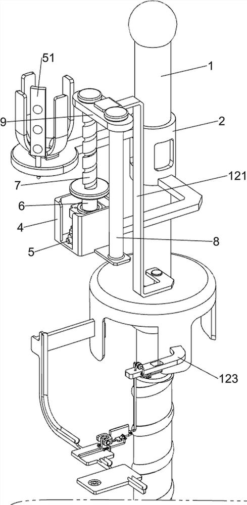
[0039] A drip infusion device that can automatically stop, such as Figure 1-8 As shown, it includes a base 1, a first mounting frame 2, a bracket 3, a second mounting frame 4, a stepping motor 5, an ultrasonic liquid level sensor 51, a first rotating shaft 6, a threaded rod 7, a first guide rod 8, a first A sliding block 9, a cable rack 10, a stop mechanism 11 and an auxiliary mechanism 12, the upper part of the base 1 is provided with a first installation frame 2, and the upper side of the front part of the first installation frame 2 is connected with a bracket 3 and an ultrasonic liquid level sensor 51, The material of the bracket 3 is aluminum alloy, which is light in weight and hard in strength. The second mounting frame 4 is bolted to the right side of the lower part of the first mounting frame 2, and the first guide rod is bolted to the upper side of the right front part of the second mounting frame 4. 8. The upper part of the first guide rod 8 is slidably set with the fi...
Embodiment 2
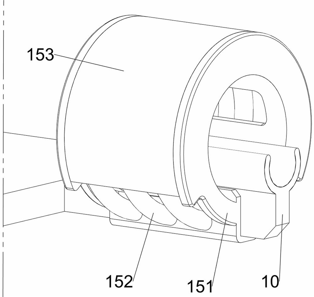
[0044] On the basis of Example 1, such as figure 1 and Figure 9 As shown, an adjustment mechanism 13 is also included. The adjustment mechanism 13 includes an installation frame 131 and an adjustment rod 132. The installation frame 131 is bolted to the right side of the lower part of the cable rack 10. Both sides of the installation frame 131 are provided with chute slots. The slots are arranged in a downward sloping manner on the left side, and an adjusting rod 132 slides through between the two slide slots.
[0045] The operator passes the infusion tube through the installation frame 131. When infusion is being performed, the operator moves the adjustment lever 132 to the left, and the adjustment lever 132 will move along the chute on the installation frame 131, because the chute is in a downward-sloping left part. setting, so the adjustment rod 132 will move downwards and squeeze the infusion tube, so that the infusion speed can be adjusted through the adjustment rod 132,...
Embodiment 3
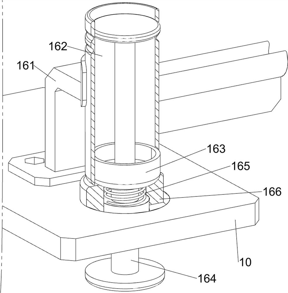
[0047] On the basis of Example 2, such as figure 1 , Figure 10 and Figure 11 As shown, a reminder mechanism 14 is also included, and the reminder mechanism 14 includes a second installation block 141, a third spring 142 and a clicker 143, and the left and right sides of the lower part of the cable rack 10 are symmetrically provided with the second installation block 141 through screws. The second mounting blocks 141 on both sides are respectively located at the front left and the front right of the rotating plate 113, the upper side of the second mounting block 141 is connected with a third spring 142, and the rear end of the third spring 142 is connected with a clicker 143, and the rotating plate 113 can be in contact with a clicker 143 .
[0048] When the injection solution in the hanging bottle is used up, the rotating plate 113 rotates counterclockwise to strike the clicker 143, the clicker 143 makes a sound under force, and the clicker 143 will move downward under for...
PUM
 Abstract
Description
Claims
Application Information