
Automatic lubricating system for movable blade and fixed blade of push shear head

An automatic lubricating and moving blade technology, applied in the field of beauty and hairdressing appliances, can solve the problems of weakened blade sharpness, unreasonable structural design, weakened shear performance, etc., so as to avoid sharpness and life reduction, improve convenience, and improve stability. sexual effect

Pending Publication Date: 2022-05-10
美国华尔推剪公司
View PDF1 Cites 0 Cited by
  • Summary
  • Abstract
  • Description
  • Claims
  • Application Information

AI Technical Summary

Problems solved by technology

In the prior art, most electric clippers, hair trimmers, pet trimmers and electric trimming tools, etc. have the temperature of the cutter head, poor cutting sharpness, manual oiling / grease troublesome (some users never oil / grease) )
Due to the high temperature generated by the reciprocating motion of the blade, if there is no lubricating oil / grease protection, the temperature of the cutter head will be too high, which will damage the edge of the blade, thereby weakening the sharpness of the blade, causing seizures and pulls.
[0003] At present, the traditional electric clippers have defects such as short life, easy to get hot, and poor customer experience: First, the reciprocating motion between the blades vibrates to generate high heat, which causes each gear to cut The performance and the temperature rise of the cutter head are very different; the second is that the reciprocating motion and vibration between the blades generate a large magnetic adsorption force, which causes the shear performance of each gear to weaken
[0005] The inventor believes that the lubricating effect of the electric clipper head in the prior art is poor, the structural design is unreasonable, and there is room for improvement

Method used


Image

  • Automatic lubricating system for movable blade and fixed blade of push shear head
  • Automatic lubricating system for movable blade and fixed blade of push shear head
  • Automatic lubricating system for movable blade and fixed blade of push shear head

Examples


Embodiment 1

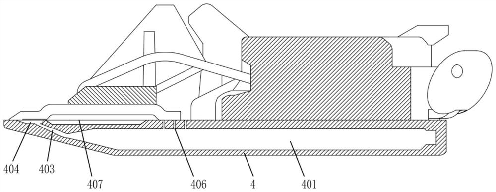
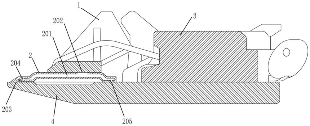
[0041] like figure 1 and figure 2 As shown, an automatic lubricating system for a movable blade and a fixed blade for pushing a scissor head provided by the present invention includes a fixed blade 4 with a first oil storage cavity 401 inside, a second oil storage cavity 201 inside a fixed blade 4 For the movable blade 2, the teeth of the movable blade 2 are located above the teeth of the fixed blade 4, and the movable blade 2 and the fixed blade 4 can reciprocate relative to each other. A first oil storage structure is formed on the side of the interdental edge surface of the fixed blade 4 close to the movable blade 2 , the first oil storage structure is communicated with the first oil storage cavity 401 , and the interdental edge surface of the movable blade 2 is close to the fixed blade 4 A second oil storage structure 203 is formed on one side of the device, and the second oil storage structure 203 communicates with the second oil storage cavity 201 .

[0042] The greas...

Embodiment 2

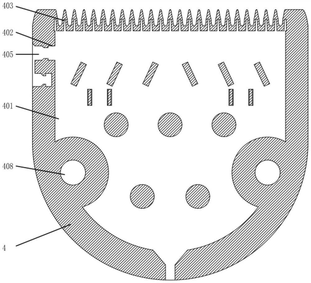
[0056] like image 3 and Figure 4 As shown, based on Embodiment 1, according to an automatic lubricating system for a movable blade and a fixed blade for pushing a scissor head provided by the present invention, one end of the fixed blade 4 is formed with a tooth portion, and the open port of the oil storage tank 404 is located at the end of the tooth portion. upper surface. The first oil filling port 402 is formed on the side wall of the stationary blade 4 , and the position of the first oil filling port 402 can be set according to the size of the first oil storage cavity 401 . 401 is filled with grease, so that the user can quickly add grease to the pushing scissors head, and the long-term supply of grease can be ensured after one-time grease addition, and there is no need to add grease to the movable blade 2 and the fixed blade 4 during use. The first oil filling port 402 is fitted with a first plug 405 for closing or opening the first oil filling port 402 to avoid leaka...

Embodiment 3

[0065] like figure 1 and figure 2 As shown, based on Embodiment 2, a push scissor head provided according to the present invention further includes a spring assembly, a blade support 3 and a guide block 1, and the spring assembly, the blade support 3 and the guide block 1 are all installed on the fixed On the upper surface of the blade 4, the tooth end of the movable blade 2 is located above the tooth end of the fixed blade 4, and the spring assembly is used to drive the movable blade 2 to move relative to the fixed blade 4, and the guide block 1 and the blade support 3 are used to limit the movable blade. 2 movements.

[0066] working principle

[0067] Before using the scissor head, open the first plug 405, and add grease to the first oil storage cavity 401 through the first oil filling port 402. After filling, use the plug 405 to close the oil filling port 402 and open the second plug. Add grease to the second oil storage cavity 201 through the second oil filling port 2...


PUM


Abstract

The invention provides an automatic lubricating system for a movable blade and a fixed blade of a hair clipper head, and relates to the field of hairdressing and beauty appliances, the automatic lubricating system comprises the fixed blade with a first oil storage cavity inside and the movable blade with a second oil storage cavity inside; a first oil storage structure is formed on the side, close to the movable blade, of the inter-tooth blade face of the fixed blade and communicates with the first oil storage cavity, and a second oil storage structure is formed on the side, close to the fixed blade, of the inter-tooth blade face of the movable blade and communicates with the second oil storage cavity. The fixed blade and the movable blade are each provided with a communication channel used for connecting the first oil storage cavity and the second oil storage cavity. The purpose of automatically lubricating the tool bit can be achieved, the tool bit is lubricated for a long time, oil is continuously supplied, the situations that the sharpness of the tool bit is reduced, the service life of the tool bit is shortened and the temperature rise is increased due to dry grinding between the movable blade and the fixed blade are avoided, and the situation that grease is frequently and directly injected on the tool bit manually to lubricate the blades is eliminated.

Description

technical field [0001] The invention relates to the field of beauty and hairdressing appliances, in particular to an automatic lubricating system for a movable blade and a fixed blade for pushing scissor heads. Background technique [0002] The hair clipper is one of the common tools in beauty salons, and it is also a familiar tool required by the public for haircuts and beauty. In the prior art, most of the electric clippers, hair trimmers, pet trimmers and electric trimming tools have the temperature of the cutter head, poor cutting sharpness, and troublesome manual oil / grease (some users never refuel / grease). ). Due to the high temperature generated by the reciprocating motion of the blade, if there is no lubricating oil / grease protection, the temperature of the blade head will be too high, which will damage the blade edge, thereby weakening the sharpness of the blade, causing the phenomenon of hair clipping and hair pulling. [0003] At present, the traditional electri...

Claims


Application Information

Patent Timeline
IPC IPC(8): B26B19/28B26B19/40
CPCB26B19/28B26B19/40
Inventor 方国宝黄泽江丁绍平
Owner 美国华尔推剪公司
Learn More