Adjustable trolley for intelligent manufacturing and production
An intelligent manufacturing and adjustable technology, applied in the direction of trolleys, trolley accessories, multi-axis trolleys, etc., can solve the problems of lack of physical strength, high labor intensity, time-consuming and laborious manual cleaning, etc., to reduce labor intensity, eliminate safety hazards, and facilitate recycling The effect of reuse
- Summary
- Abstract
- Description
- Claims
- Application Information
AI Technical Summary
Problems solved by technology
Method used
Image
Examples
Embodiment 1
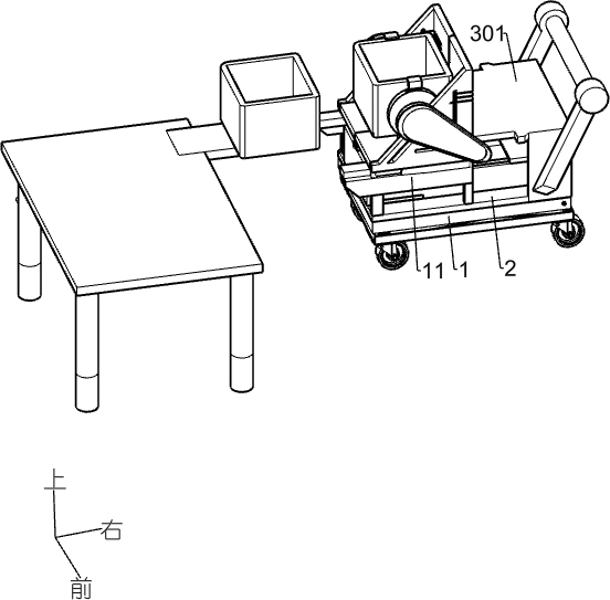
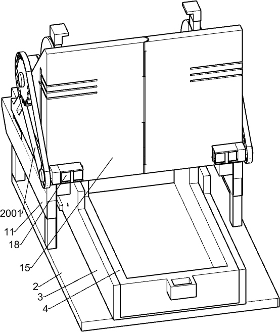
[0027] An adjustable smart manufacturing production cart such as Figure 1-Figure 3 As shown, it includes lifting frame 1, base plate 2, material storage box 3, protective shell 301, material receiving box 4, carrying plate 5, clamping mechanism and crushing mechanism, lifting frame 1 is an existing lifting device, lifting frame 1 is equipped with four rollers that are easy to move, the lifting frame 1 is fixedly connected with a base plate 2, the base plate 2 is fixedly connected with a material storage box 3, the base plate 2 is equipped with a protective shell 301, and the protective shell 301 is equipped with a Push the handle of the cart, the material storage box 3 is slidingly connected with the material receiving box 4, and the material receiving box 4 is used to collect the crushed waste, the material receiving box 4 is similar to a drawer, and the material storage box 3 is fixed with a bearing plate 5. The carrying plate 5 is connected with a clamping mechanism, and t...
Embodiment 2
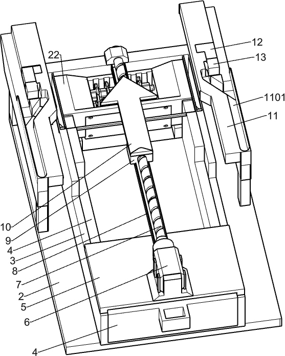
[0030] On the basis of Example 1, such as image 3 , Figure 4 , Figure 6 and Figure 7 As shown, the clamping mechanism includes a power motor 6, a screw mandrel 7, a first guide rail 8, a screw nut 9, an arrow block 10, a box bracket 11, a first slideway 1101, an electric push rod 12, a blocking block 13, a second One box body 14, the second box body 15, the first clamp block 16, the second clamp block 1601, the fixed block 1602 and the connection tension spring 1701, the power motor 6 is installed on the load plate 5, and the rotating shaft of the power motor 6 is fixedly connected There is a screw mandrel 7, and one end of the screw mandrel 7 away from the power motor 6 is rotatably connected to the bearing seat on the material storage box 3, and the bearing seat is arranged on the left side frame of the material storage box 3, and the bearing plate 5 is fixedly connected with The first guide rail 8, the end of the first guide rail 8 away from the bearing plate 5 is af...
Embodiment 3
[0033] On the basis of Example 2, such as Figure 9 , Figure 10 , Figure 11 and Figure 12 As shown, the crushing mechanism includes a crushing box 22, a variable speed motor 23, a third gear 2301, a crusher 24, a fourth gear 2401, a middle shaft 25, a scraper torsion spring 2501, a scraper spring 26, a lower bar 27, an upper Slide bar 28, power rod 29 and scraper plate 30, crushing box body 22 is installed in the material storage box 3, and the top of crushing box body 22 has the slope of inclination, thereby facilitates waste material to slide in the breaking box, and the crushing box body 22 A variable speed motor 23 is installed, a third gear 2301 is installed on the rotating shaft of the variable speed motor 23, a crusher 24 is installed in the crushing box 22, the crusher 24 is the prior art, and a fourth gear 2301 is installed on the power input shaft of the crusher 24 Gear 2401, the third gear 2301 and the fourth gear 2401 are meshed, and the front and rear side w...
PUM
 Abstract
Description
Claims
Application Information
 - R&D
- Intellectual Property
- Life Sciences
- Materials
- Tech Scout
- Unparalleled Data Quality
- Higher Quality Content
- 60% Fewer Hallucinations
Browse by: Latest US Patents, China's latest patents, Technical Efficacy Thesaurus, Application Domain, Technology Topic, Popular Technical Reports.
© 2025 PatSnap. All rights reserved.Legal|Privacy policy|Modern Slavery Act Transparency Statement|Sitemap|About US| Contact US: help@patsnap.com


