
Temperature control debugging device for power battery system

A power battery and system temperature technology, applied in battery temperature control, secondary batteries, circuits, etc., can solve problems such as increased temperature fluctuations in experimental chambers and inability to simulate, to speed up development progress, optimize design, and minimize temperature control. The effect of energy consumption

Pending Publication Date: 2022-05-10
DONGFENG COMML VEHICLE CO LTD
View PDF0 Cites 1 Cited by
  • Summary
  • Abstract
  • Description
  • Claims
  • Application Information

AI Technical Summary

Problems solved by technology

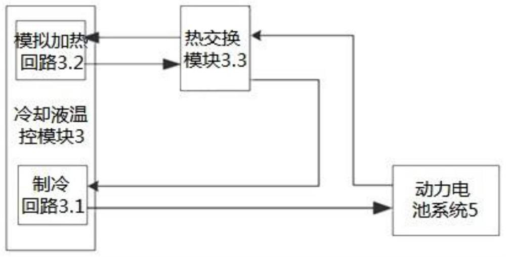
[0006] When the battery system, vehicle controller, and temperature control unit are placed together in the high and low temperature test chamber, and when the joint debugging test is carried out by simulating the working conditions of the vehicle, the heat emitted by the temperature control unit is directly discharged into the test chamber, which will cause the test The temperature fluctuation in the cabin increases; during the actual driving process of the whole vehicle, the radiator of the battery cooling unit basically has a certain head-on wind speed and has taken away the heat. The existing experimental cabin cannot simulate such a situation

Method used


Image

  • Temperature control debugging device for power battery system
  • Temperature control debugging device for power battery system
  • Temperature control debugging device for power battery system

Examples


Embodiment Construction

[0044] The specific embodiments of the present invention will be further described below in conjunction with the accompanying drawings. It should be noted here that the descriptions of these embodiments are used to help understand the present invention, but are not intended to limit the present invention. In addition, the technical features involved in the various embodiments of the present invention described below may be combined with each other as long as they do not constitute a conflict with each other.

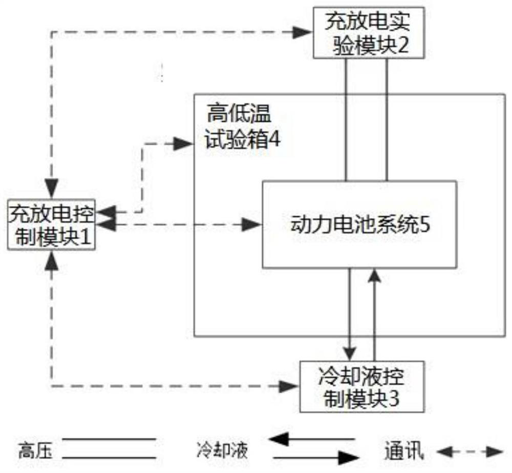
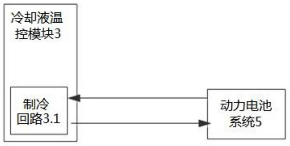
[0045] like figure 1 As shown, the present invention provides a power battery system temperature control debugging device, through communication and corresponding host computer software, the charge and discharge test module 2, high and low temperature test chamber 4, coolant temperature control module 3 and power battery system 5 , integrated in a control interface for linkage control, which can simulate different temperature environments and actual charging and dischar...


PUM


Abstract

The invention discloses a temperature control debugging method and device for a power battery system. The system comprises a charging and discharging control module which is used for monitoring temperature and humidity information in a high and low temperature test box and information of a power battery system, sending a charging and discharging command to a charging and discharging test module according to the monitored information of the power battery system, and sending a temperature control command to a cooling liquid temperature control module; sending a temperature control command to the high and low temperature test box according to the temperature and humidity information; the charging and discharging experiment module is used for controlling the power battery system to charge and discharge according to the charging and discharging command; the cooling liquid temperature control module is used for controlling the temperature of the power battery system according to the temperature control command; and the high-low temperature test box is used for adjusting temperature and humidity in the box according to the temperature and humidity command. According to the invention, the temperature control strategy / temperature control unit design can be continuously optimized, the temperature control energy consumption is minimized, and the driving range of the whole vehicle is prolonged, so that the temperature control development progress of the power battery is accelerated, and the test time of the whole vehicle is shortened.

Description

technical field [0001] The invention belongs to the technical field of power battery thermal management, and in particular relates to a power battery system temperature control debugging device. Background technique [0002] At present, the cooling system of the power battery system for new energy vehicles mostly adopts a liquid cooling system, but how to keep the power battery system working in the optimal temperature range under various working conditions, ensure the safety of the power battery system and prolong the life of the battery system, At the same time, continuously reducing the power consumption of liquid-cooled batteries and extending the driving range of electric vehicles has always been a problem that requires continuous optimization by vehicle manufacturers. In the past, there was no suitable bench, and the temperature control strategy could only be corrected by using the actual vehicle test, but this method was time-consuming and labor-intensive, which delay...

Claims


Application Information

Patent Timeline
Patent Type & Authority Applications(China)
IPC IPC(8): H01M10/613H01M10/63H01M10/6563H01M10/625H01M10/65
CPCH01M10/613H01M10/63H01M10/6563H01M10/625H01M10/65
Inventor 冯修成孟仙雅孟国栋宋宏贵柯炯
Owner DONGFENG COMML VEHICLE CO LTD
Learn More