
Optical path control member

A technology for controlling components and optical paths, applied in optical components, optics, circuits, etc., can solve the problems of reduced light blocking characteristics of switchable light-shielding films, low voltage of power connection unit, limited use range of switchable light-shielding films, etc.

Pending Publication Date: 2022-05-10
LG INNOTEK CO LTD
View PDF0 Cites 0 Cited by
  • Summary
  • Abstract
  • Description
  • Claims
  • Application Information

AI Technical Summary

Problems solved by technology

However, since the switchable light-shielding film is fixed to a specific display device, there is a problem that the range of use of the switchable light-shielding film is limited
[0007] In addition, when a portable switchable light-shielding film is applied, there is a problem that the light-blocking property of the switchable light-shielding film is lowered due to the low voltage applied to the power connection unit.

Method used


Image

  • Optical path control member
  • Optical path control member
  • Optical path control member

Examples


Embodiment Construction

[0029] Hereinafter, embodiments of the present invention will be described in detail with reference to the accompanying drawings. However, the spirit and scope of the present invention are not limited to part of the described embodiments, and may be implemented in various other forms, and one or more of the embodiments may be selectively combined and replaced within the spirit and scope of the present invention elements.

[0030] In addition, unless otherwise clearly defined and described, the terms (including technical terms and scientific terms) used in the embodiments of the present invention can be interpreted as the same meaning as commonly understood by those of ordinary skill in the art to which the present invention belongs, and for example, in the general dictionary Terms defined in may be interpreted to have meanings consistent with their meanings in the relevant technical context.

[0031] In addition, terms used in the embodiments of the present invention are used...


PUM

PropertyMeasurementUnit
heightaaaaaaaaaa
widthaaaaaaaaaa
widthaaaaaaaaaa

Abstract

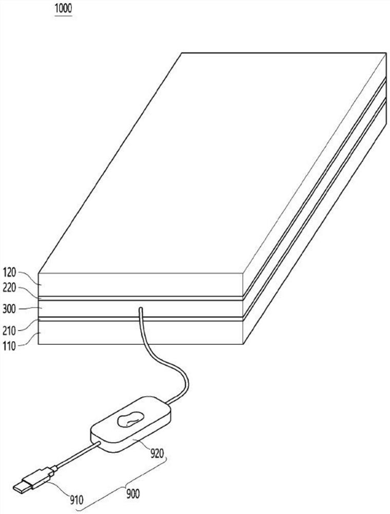
An optical path control member according to an embodiment includes: a first substrate; a first electrode disposed on the first substrate; the second substrate is arranged on the first substrate; a second electrode disposed under the second substrate; a light conversion unit disposed between the first electrode and the second electrode; and a power supply unit connected to the first electrode and the second electrode, in which the light conversion unit includes partition wall units and accommodating units alternately arranged, a light transmittance of the accommodating units is changed in response to an application of a voltage, the accommodating units include a dispersion liquid and a plurality of light absorbing particles dispersed in the dispersion liquid, a height of the accommodating units is 15 [mu] m to 25 [mu] m, and the light absorbing particles are dispersed in the dispersion liquid. The width of the accommodating unit is 1.5 [mu] m to 2.5 [mu] m, and the power supply unit includes a power supply connection unit for connecting an external power supply and the light conversion unit, and a power supply switching unit for turning on / off the transmission of a voltage.

Description

technical field [0001] Embodiments relate to an optical path control member capable of controlling a viewing angle of emitted light. Background technique [0002] The light-shielding film shields the transmission of light from the light source, and is attached to the front of the display panel as a display device for mobile phones, notebook computers, tablet computers, car navigation devices, car touch screens, etc., so that when the display broadcasts what is displayed on the screen When displaying content, the shading film adjusts the viewing angle of the light according to the incident angle of the light, so as to show clear image quality at the viewing angle required by the user. [0003] In addition, the light-shielding film may be used for windows of vehicles, buildings, etc., to partially block external light to prevent glare, or to prevent the inside from being seen from the outside. [0004] That is, the light shielding film may be an optical path control member th...

Claims


Application Information

Patent Timeline
Patent Type & Authority Applications(China)
IPC IPC(8): G02F1/167G02F1/1675G02F1/1676G02F1/1685G02F1/1679G02F1/1347H01L27/32
CPCG02F1/167G02F1/1675G02F1/1676G02F1/1685G02F1/1679G02F1/1347H10K59/50G02B5/30G02B26/08G02F1/1323G02F1/1681
Inventor 韩伶妵李仁会金柄淑
Owner LG INNOTEK CO LTD
Learn More