Combined tube clamping device for fixing thoracic duct

A chest tube and chassis technology, applied in the direction of catheters, etc., can solve the problems of inconvenient cleaning, poor comfort, inflexible adjustment and repeated use, etc., and achieve the effect of easy adjustment and removal, and comfortable use

Inactive Publication Date: 2022-05-13
SHANGHAI PULMONARY HOSPITAL
View PDF0 Cites 0 Cited by
  • Summary
  • Abstract
  • Description
  • Claims
  • Application Information

AI Technical Summary

Problems solved by technology

[0004] The object of the present invention is to provide a chest tube fixation combined clamping device, which solves the problem that the existing chest tube clamping tube is fixed by adhesive tape, which is poor in use comfort, inconvenient to clean, and cannot be flexibly adjusted and reused

Method used


Image

  • Combined tube clamping device for fixing thoracic duct
  • Combined tube clamping device for fixing thoracic duct
  • Combined tube clamping device for fixing thoracic duct

Examples


Embodiment 1

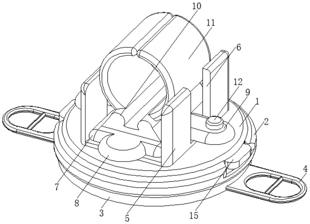
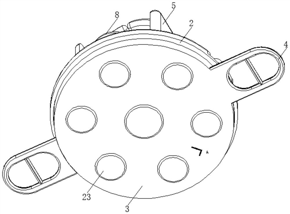
[0025] see Figure 1-6 , the present invention provides a technical solution: a chest tube fixing joint clamping device, including a chassis 1, a collar 2, a base 3, and a rubber sheet 23, the left and right sides of the base 3 are fixedly connected with hanging rings 4, and the upper part of the chassis 1 The end face is fixedly connected with a square card frame 5, which is characterized in that the left and right sides of the square card frame 5 are provided with limit slides 6, and the square card frame 5 is slidingly provided with a support plate 7, and the front and rear sides of the support plate 7 are respectively fixed. The lifting plate 8 is connected, and the left and right sides of the support plate 7 are fixedly connected with the slide plate 9, and the left and right sides of the upper end surface of the support plate 7 are fixedly equipped with hinged seats 10, and are connected with arc-shaped clamping plates through the hinged seats 10. 11. The sliding plate 9...

Embodiment 2

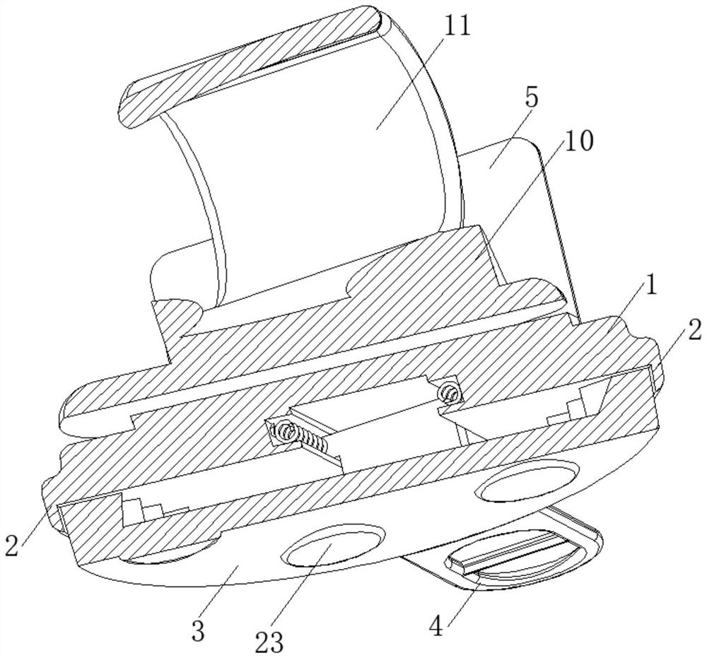
[0028] see Figure 1-6As shown, on the basis of Embodiment 1, the present invention provides a technical solution: the slide rail 13 is extended in the diameter direction of the lower end surface of the chassis 1, and each slide block 15 is slidably arranged in the slide rail 13, and the slide block 15 The front and rear sides limit slides in the limit groove 14 that slide rail 13 front and rear sides inner wall offers, and the slide block 15 of left and right sides is close to each other between the front and rear ends of a side and between the inner wall of the limit groove 14 of front and rear sides respectively. A spring 20 is fixedly connected between them, and the ends of the sliders 15 on the left and right sides that are far away from each other extend through the slide rail 13 on the outside of the chassis 1, and the connecting block 16 that is fixedly connected to the lower end of the slider 15 extends in the base 3 and extends The end is fixedly connected with a mov...


PUM


Abstract

The invention discloses a thoracic duct fixing combined tube clamping device, relates to the field of thoracic duct clamping devices, and solves the problems that an existing thoracic duct clamping tube is fixed by adopting an adhesive tape, so that the use comfort is poor, the thoracic duct clamping tube is inconvenient to clean, and the thoracic duct clamping tube cannot be flexibly adjusted and reused. The device comprises a chassis, a lantern ring, a base, a rubber sheet, a hanging ring, a square clamping frame, a limiting sliding way, a supporting plate, a lifting plate and a sliding plate, hinge seats are fixedly installed on the left side and the right side of the upper end face of the supporting plate, arc-shaped clamping plates are rotationally connected through the hinge seats, the sliding plate is rotationally sleeved with a positioning bolt, and a sliding rail is formed in the lower end face of the chassis in a penetrating mode. Limiting grooves are formed in the left ends and the right ends of the inner walls of the front side and the rear side of the sliding rail correspondingly, sliding blocks are slidably arranged at the two ends of the sliding rail correspondingly, and rotation adjusting mechanisms are arranged between the sliding blocks and the base. The device has the advantages of being comfortable to use, convenient to adjust, stable in clamping and capable of being adjusted for multiple times.

Description

technical field [0001] The invention relates to the field of chest tube clamping devices, in particular to a chest tube fixing combined tube clamping device. Background technique [0002] In thoracic surgery, most of the patients treated are lung cancer surgery patients and chest trauma surgery patients. After the operation, the patients routinely indwell the chest cavity closed drainage device. In the process of indwelling the chest tube, chest tube clamping operation is also required if necessary. [0003] In the current chest tube fixation method, 3M elastic soft wide tape is usually used to paste the chest tube, and the method of clamping the chest tube is mostly to fold the chest tube and wrap it with tape or tie it with a tourniquet, but such a chest tube There are some disadvantages in the fixing and clamping method, because the tape is easy to fall off during long-term use, and the stability of use is poor, and the adhesive tape is pasted and fixed on the human body...

Claims


Application Information

Patent Timeline
Patent Type & Authority Applications(China)
IPC IPC(8): A61M25/02
CPCA61M25/02A61M2025/028
Inventor 洪胜兰
Owner SHANGHAI PULMONARY HOSPITAL
Why Eureka
Try Eureka