
Equipment for automatically pressing oil-retaining bearing in motor shell

A motor housing and bearing technology, applied in the direction of electromechanical devices, electric components, metal processing equipment, etc., can solve the monitoring of no working parameters, can not guarantee the dimensional tolerance of inner hole and coaxiality, cylindricity, motor stall, etc. problems, to achieve the effect of improving production efficiency, improving assembly quality, and convenient maintenance

Pending Publication Date: 2022-05-13
GUIYANG WANJIANG AVIATION ELECTROMECHANICAL
View PDF0 Cites 0 Cited by
  • Summary
  • Abstract
  • Description
  • Claims
  • Application Information

AI Technical Summary

Problems solved by technology

[0002] At present, the oil-impregnated bearing (powder metallurgy) is pressed into the motor housing of the windshield wiper of the car, and the material cannot be transferred completely automatically. It is carried out on the motor assembly line along the line, and only the outer circle of the oil-impregnated bearing and the motor housing are press-fitted. The interference fit of the inner circle of the top is to assemble the oil-impregnated bearing in the motor housing. There are no effective process guarantees and no monitoring of industrial parameters during the entire assembly process. Highness and cylindricity requirements, unstable quality, low efficiency, and the current oil injection process from bottom to top cannot guarantee the quantitative controllable amount of oil injection, resulting in a certain number of motor housing parts in the oil bearings after press-fitting The hole cannot be inserted into the armature worm and the motor is blocked after the motor is assembled.

Method used


Image

  • Equipment for automatically pressing oil-retaining bearing in motor shell
  • Equipment for automatically pressing oil-retaining bearing in motor shell
  • Equipment for automatically pressing oil-retaining bearing in motor shell

Examples


Embodiment Construction

[0036] The following will clearly and completely describe the technical solutions in the embodiments of the present invention with reference to the accompanying drawings in the embodiments of the present invention. Obviously, the described embodiments are only some, not all, embodiments of the present invention. Based on the embodiments of the present invention, all other embodiments obtained by persons of ordinary skill in the art without making creative efforts belong to the protection scope of the present invention.

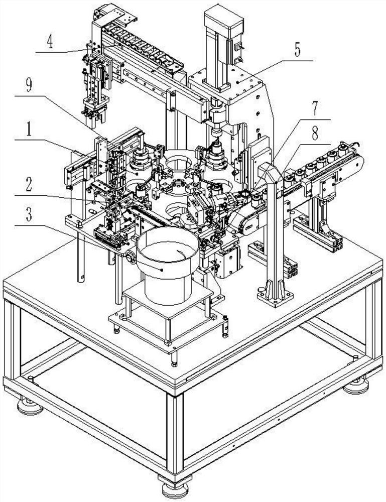
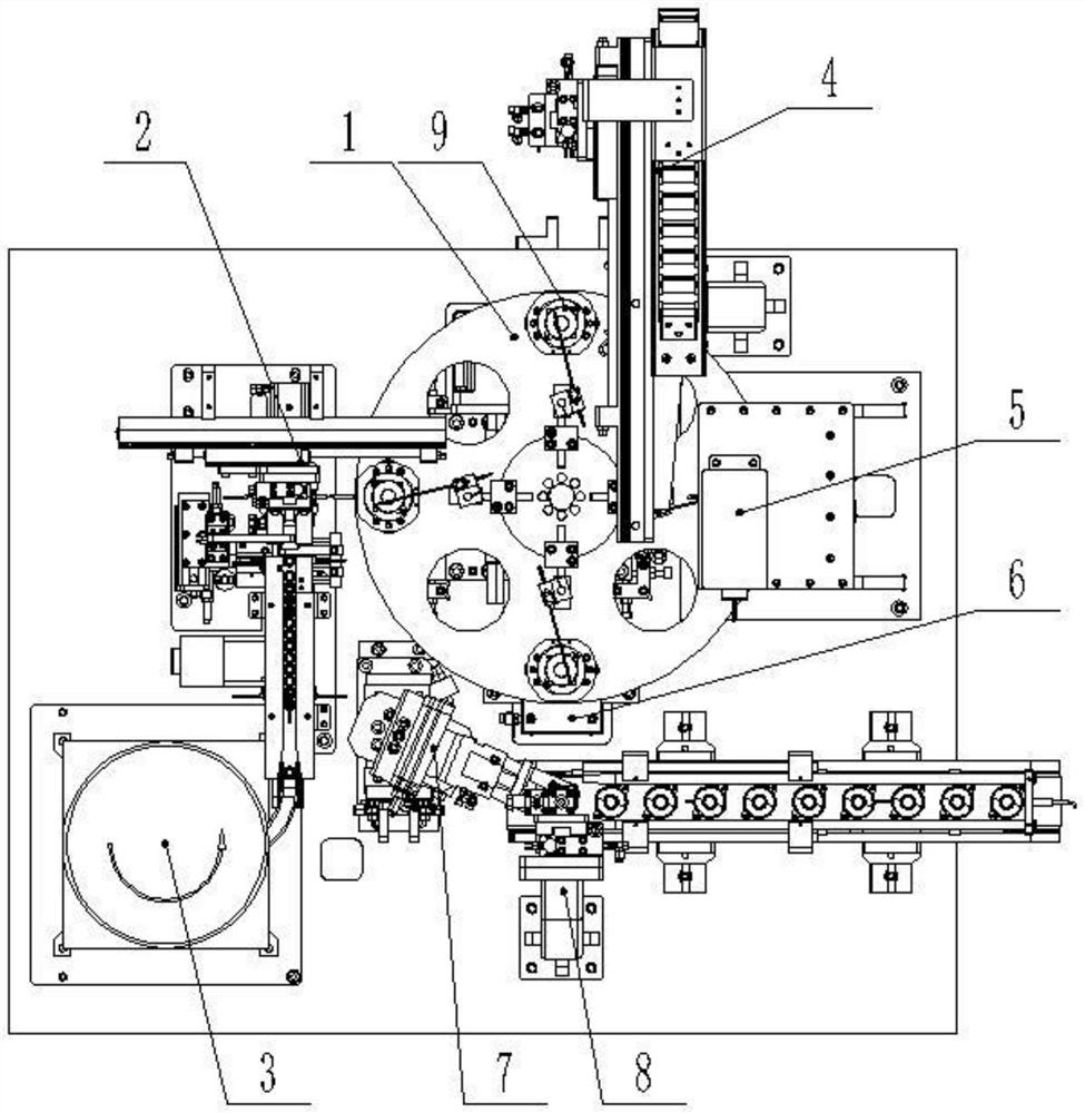
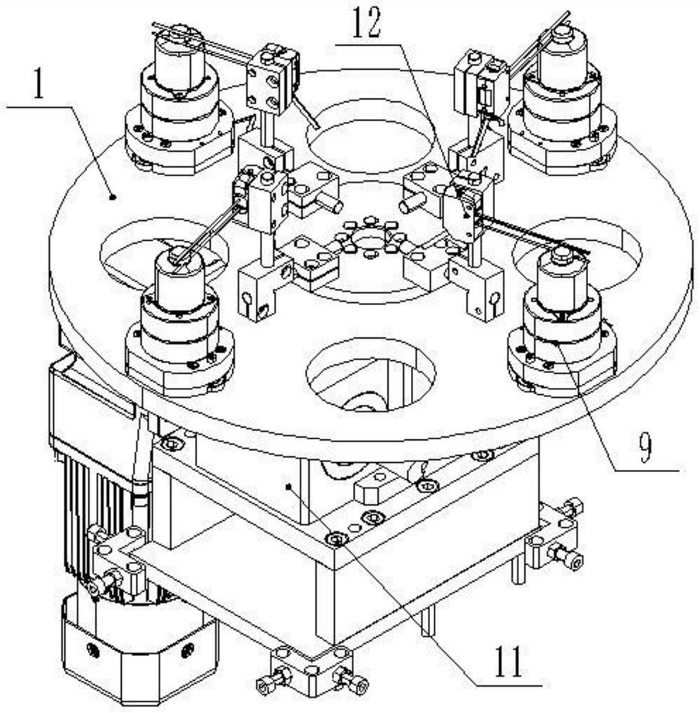
[0037] see figure 1 and figure 2 , a kind of automatic press-fit oil bearing equipment in the motor shell, including indexing plate 1, feeding mechanism 2, feeding plate 3, shell feeding mechanism 4, press machine 5, loosening mechanism 6, material taking mechanism 7, oil injection Mechanism 8 and mold 9, the indexing plate 1, feeding mechanism 2, feeding plate 3, shell feeding mechanism 4, press 5, loosening mechanism 6, material taking mechanism 7 and oili...


PUM


Abstract

The invention discloses equipment for automatically press-fitting an oil bearing in a motor shell, which comprises an index plate, dies, a feeding mechanism, a shell conveying mechanism, a press, a loosening mechanism, a material taking mechanism and an oil injection mechanism, the dies are uniformly distributed and mounted on the outer side of the upper end of the index plate, and the dies are used for placing the motor shell; the feeding mechanism is used for sequentially placing oil bearings on a mold, the shell conveying mechanism is used for placing a motor shell on the mold, the pressing machine is used for pressing the oil bearings into the motor shell, and the loosening mechanism is used for pulling out a positioning shaft at the upper end of a guide rod from the oil bearings. The material taking mechanism is used for taking down the pressed motor shell from the mold, and the oil injection mechanism is used for injecting lubricating oil into the motor shell. According to the oil bearing press-fitting device, the functions of hole extrusion and shape correction of an inner hole in the oil bearing press-fitting process are added, automatic taking, placing, positioning and transferring of all materials are achieved, the assembly quality is greatly improved, and the production efficiency is greatly improved.

Description

technical field [0001] The invention relates to the technical field of press-fitting of motor housings, in particular to equipment for automatically press-fitting oil-impregnated bearings in motor housings. Background technique [0002] At present, the oil-impregnated bearing (powder metallurgy) is pressed into the motor housing of the automobile windshield wiper, and the material cannot be transferred completely automatically. It is carried out on the motor assembly line along the line, and only the outer circle of the oil-impregnated bearing and the motor housing are press-fitted. The interference fit of the inner circle of the top is to assemble the oil-impregnated bearing in the motor housing. There are no effective process guarantees and no monitoring of industrial parameters during the entire assembly process. Highness and cylindricity requirements, unstable quality, low efficiency, and the current oil injection process from bottom to top cannot guarantee the quantitat...

Claims


Application Information

Patent Timeline
Patent Type & Authority Applications(China)
IPC IPC(8): B23P19/00B23P19/027B23P23/00H02K15/00
CPCB23P19/001B23P19/027B23P23/00H02K15/00
Inventor 梅大云杨迅
Owner GUIYANG WANJIANG AVIATION ELECTROMECHANICAL
Features
  • Generate Ideas
  • Intellectual Property
  • Life Sciences
  • Materials
  • Tech Scout
  • Unparalleled Data Quality
  • Higher Quality Content
  • 60% Fewer Hallucinations
Learn More