Sewage treatment tank with steel fixing structure

A sewage treatment pool and fixed structure technology, which is applied in water/sewage treatment, water/sewage treatment equipment, water/sludge/sewage treatment, etc., can solve the problem of poor desilting and sludge diversion effects affecting the water quality of sewage treatment pools Purification effect and other issues, to achieve the effect of improving mud removal effect and mud discharge efficiency, good sludge diversion effect, and good water purification performance

Pending Publication Date: 2022-05-13
海口永祺环保设备技术有限公司
View PDF0 Cites 0 Cited by
  • Summary
  • Abstract
  • Description
  • Claims
  • Application Information

AI Technical Summary

Problems solved by technology

[0004] The purpose of the present invention is to address the deficiencies in the above-mentioned technologies, and propose a sewage treatment tank with a steel fixed structure, aiming at solving the problem of poor sludge removal and sludge diversion effects of the above-mentioned sewage treatment tank. The problem of water purification effect

Method used


Image

  • Sewage treatment tank with steel fixing structure
  • Sewage treatment tank with steel fixing structure
  • Sewage treatment tank with steel fixing structure

Examples


Embodiment 1

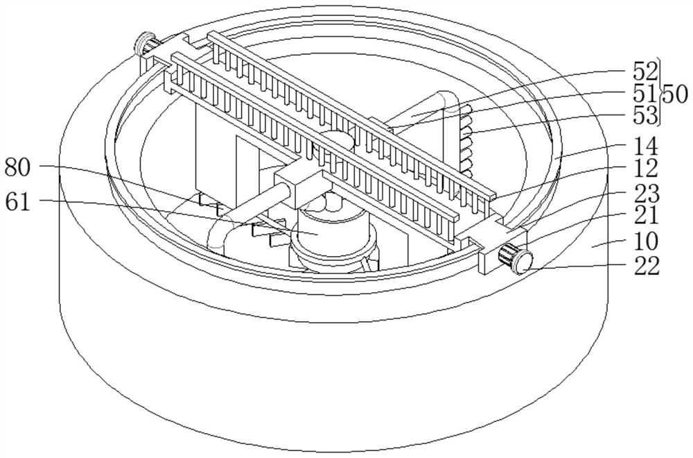
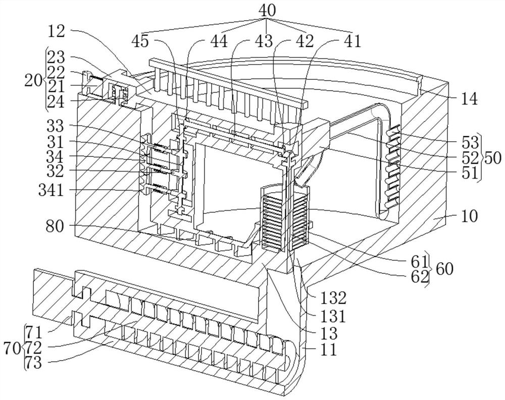
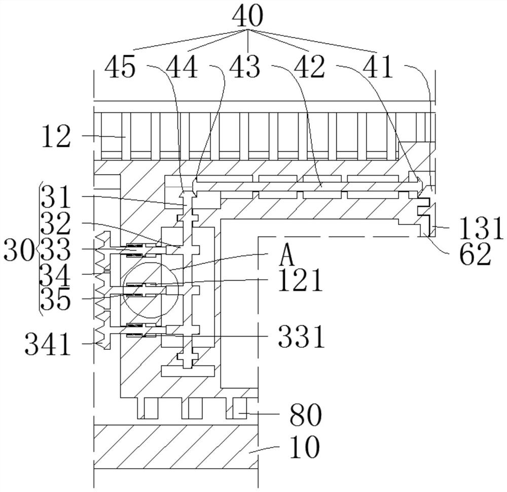
[0034] refer to Figure 1 to Figure 6 , the invention provides a sewage treatment tank with a steel fixed structure, comprising:

[0035] Pool body 10, sludge pipe 11, turret 12 and center platform 13 are arranged on the pool body 10, turret 12 is rotatably installed on the center platform 13, and turret 12 is provided with a drive mechanism 20 for driving turret 12 to rotate ;

[0036] The desilter mechanism 30, the desilter mechanism 30 is arranged on the turret 12 and can crush the sludge on the side wall of the tank body 10;

[0037] The transmission mechanism 40, the transmission mechanism 40 is arranged on the turret 12 and can cooperate with the rotation process of the turret 12 to drive the mud removal mechanism 30 to perform mud scraping work;

[0038] A mud suction mechanism 50, the mud suction mechanism 50 is arranged on the turret 12 and is used to collect the sludge in the tank body 10;

[0039] A mud guide mechanism 60, the mud guide mechanism 60 is arranged o...

Embodiment 2

[0050] refer to Figure 1 to Figure 6 , in conjunction with the technical scheme of embodiment 1, in the present embodiment, transmission mechanism 40 comprises central bevel gear 41, main bevel gear 42, transmission rod 43, from bevel gear 44 and transmission bevel gear 45, center table 13 is provided with center column 131, the central bevel gear 41 is arranged on the central column 131, the main bevel gear 42 meshes with the central bevel gear 41, the main bevel gear 42 and the slave bevel gear 44 are both arranged on the transmission rod 43, and the transmission rod 43 is rotatably installed on the turret 12 Above, the transmission bevel gear 45 meshes with the slave bevel gear 44, and the transmission bevel gear 45 is arranged on the rotating rod 31 and can drive the rotating rod 31 to rotate.

[0051] When the turret 12 rotates, the main bevel gear 42 revolves around the central bevel gear 41 and drives the transmission rod 43 to rotate under the action of the central be...


PUM


Abstract

The invention provides a sewage treatment tank with a steel fixing structure, which comprises a tank body, a water inlet pipe, a water outlet pipe, a sludge pipe, a rotating frame, a center table, a driving mechanism, a sludge removal mechanism, a transmission mechanism, a sludge suction mechanism, a sludge guide mechanism, a sludge discharge mechanism and a sludge scraping assembly, in the rotating process of the rotating frame, the sludge scraping assembly is driven to conduct sludge scraping work on the bottom of the pool body, the transmission mechanism drives the sludge removing mechanism to conduct sludge scraping work on sludge on the side wall of the pool body, and the sludge suction mechanism on the rotating frame concentrates the scraped sludge to the sludge guide mechanism and discharges the sludge through the sludge discharging mechanism. The sludge removal mechanism, the sludge suction mechanism and the sludge scraping assembly rotate along with the rotating frame so that comprehensive sludge removal work can be conveniently carried out on the tank body, a good sludge flow guide effect is achieved, the sludge removal effect and the sludge discharge efficiency of the tank body are improved, and good water quality purification performance is achieved.

Description

technical field [0001] The invention relates to the technical field of sewage treatment, in particular to a sewage treatment pool with a steel fixed structure. Background technique [0002] Sewage treatment is the process of purifying sewage to meet the water quality requirements for discharge into a certain water body or for reuse. Sewage treatment is widely used in various fields such as construction, agriculture, transportation, energy, petrochemical, environmental protection, urban landscape, medical care, catering, etc., and it is also increasingly entering the daily life of ordinary people. [0003] The sludge at the bottom and on the wall of the existing sewage treatment tank is not easy to be discharged in time, and its desilting and sludge diversion effects are poor. After long-term accumulation of sludge, it is easy to affect the water purification effect of the sewage treatment tank. Contents of the invention [0004] The purpose of the present invention is to ...

Claims


Application Information

Patent Timeline
Patent Type & Authority Applications(China)
IPC IPC(8): E03F11/00E03F7/00E02F5/28E02F3/88E02F3/90E02F3/92C02F1/00
CPCE03F11/00E03F7/00E02F5/28E02F5/282E02F3/8808E02F3/90E02F3/9256E02F3/9293C02F1/00C02F2201/002
Inventor 梁小柳陈德震林小军张扬陈兴柏
Owner 海口永祺环保设备技术有限公司
Why Eureka
Try Eureka