

Well head mud removing device
A swirl device and mud storage technology, applied in the field of oil and gas field exploration and development, can solve problems such as unsatisfactory treatment effect, and achieve the effects of improving mud removal effect, improving construction quality and reducing work-related incidents.
- Summary
- Abstract
- Description
- Claims
- Application Information
AI Technical Summary
Problems solved by technology
Method used
Image

Examples
Embodiment 1
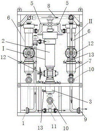
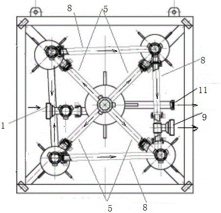
[0025] In order to overcome the unsatisfactory treatment effect of the existing mud and sand (15-74 microns) with a smaller particle size, and the original desander can no longer fully meet the requirements of high-efficiency filtration of mud and sand in the flowback liquid, the present invention provides such as figure 1 and figure 2 A wellhead desilting device is shown. This device can effectively filter out solid particles such as mud and sand, and the desilting efficiency is as high as 90%, which largely avoids the damage of mud and sand to the downstream equipment on the ground. The invention breaks through the desander principle and structure of conventional desanders, realizes two-stage separation through the combined form of one-to-four cyclone desilters, and realizes two-stage separation through the different swirl taper, processing capacity and matching of two-stage cyclones. The outlet manifold can effectively improve the desilting effect of each stage.
[0026] ...
Embodiment 2
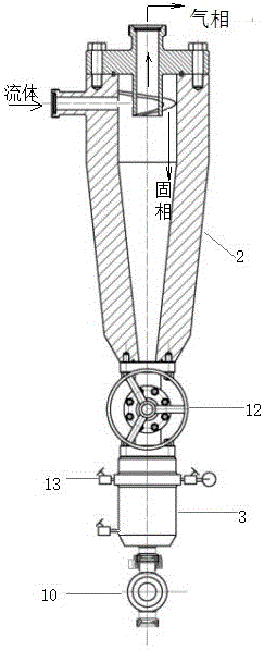
[0029] Based on the above-mentioned embodiment, in this embodiment, as image 3 As shown, the primary cyclone device I includes a primary cyclone 2 and a primary mud storage tank 3, and the primary cyclone 2 and the primary mud storage tank 3 are connected through an isolation flat valve 12. A pressure relief valve 13 is provided on the primary mud storage tank 3 , and a mud discharge cock valve 10 is provided at the lower end of the primary mud storage tank 3 . The primary cyclone device I relies on centrifugal force and gravity to separate solid particles such as mud.
[0030] The rated working pressure of the primary cyclone 2: 35MPa, the diameter of the cyclone: ø190mm, the processing capacity under the rated working pressure: 1652L / S, the diameter of the liquid inlet: ø50mm, the diameter of the liquid outlet: ø65mm, the diameter of the mud discharge port : ø52mm, cyclone cone angle: 16°, separation particle size: 45~74um, volume of primary mud storage tank 3: ≥15L.
...
Embodiment 3
[0039]Based on the above-mentioned embodiment, in this embodiment, as Figure 5 As shown, the primary mud storage tank 3 is provided with a liquid level gauge 4 .
[0040] The liquid level gauge 4 is connected with the primary mud storage tank 3 through a straight joint 14 .
[0041] The liquid level gauge 4 is a glass plate liquid level gauge with a working pressure of 35MPa.
[0042] The liquid level gauge 4 used in the device is used to measure the liquid level in the primary mud storage tank 3, which can timely and effectively remove the sludge in the primary mud storage tank 3.
[0043] Process comparison table of the original desander and the desilter device of the present invention
[0044] serial number Existing process Process of the present invention 1 A cyclone with a sand storage tank One main cyclone, four auxiliary cyclones, each cyclone is equipped with a mud storage tank 2 1 flat valve with 1 sand discharge cock 5 flat valves (Ca...
PUM
 Abstract
Description
Claims
Application Information