
Liquid crystal glass plate modulation circuit

A technology of glass plate and modulation, which is applied in the direction of instruments, static indicators, nonlinear optics, etc., can solve the problems of not reaching the function of liquid crystal voltage control circuit and poor control of liquid crystal, so as to prevent polarization fatigue and prolong the duration Effect

Pending Publication Date: 2022-05-13
KUN SHAN UNIVERSITY
View PDF0 Cites 0 Cited by
  • Summary
  • Abstract
  • Description
  • Claims
  • Application Information

AI Technical Summary

Problems solved by technology

[0003] With the development of science and technology, reducing the size of the circuit is the goal of various technology factories. However, if the traditional liquid crystal voltage control circuit is directly integrated into an IC, it often fails to achieve the functions that the liquid crystal voltage control circuit should have, and the control of the liquid crystal is still poor.

Method used


Image

  • Liquid crystal glass plate modulation circuit

Examples


Embodiment Construction

[0040] Based on the above technical features, the main functions of the liquid crystal glass panel modulation circuit of the present invention will be clearly presented in the following embodiments.

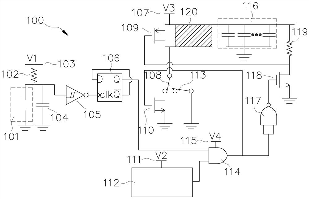
[0041] see figure 1 , revealing the liquid crystal glass plate modulation circuit 100 of the embodiment of the present invention, combined with a glass plate (not shown) to form a liquid crystal glass plate, the liquid crystal glass plate modulation circuit 100 includes: a vibration sensing component 101, an input Resistor 102, a first voltage source 103, an input capacitor 104, a Schmitt trigger circuit 105, a flip-flop 106, a third voltage source 107, a first switch 108, a second transistor 109, a A third transistor 110, a second voltage source 111, a pulse wave generation component 112, a second switch 113, a logic judgment component, a fourth voltage source 115, an output capacitor 116, a first transistor 118, a Output resistor 119 and a liquid crystal layer 120 . The logic...


PUM


Abstract

A liquid crystal glass plate modulation circuit is mainly characterized in that a vibration sensing component is triggered by knocking a glass plate, a first pulse wave is output through a Schmitt trigger circuit and a flip-flop, and a logic judgment component outputs a high voltage or a low voltage according to the first pulse wave and a second pulse wave generated by a pulse wave generation component. And a first transistor, a second transistor and a third transistor are respectively turned on or off according to the high voltage or the low voltage, so that a liquid crystal layer is changed into a first state or a second state. The liquid crystal glass plate modulation circuit can be integrated, can be conveniently applied to a minimized voltage control circuit, and has a better control effect on the liquid crystal layer.

Description

technical field [0001] The invention relates to a modulation circuit for a liquid crystal glass plate, especially a modulation circuit for changing the transparency of the liquid crystal layer by applying high voltage to the positive and negative poles of the liquid crystal layer. Background technique [0002] Traditional liquid crystal voltage control circuits are all high-voltage drive circuits. In order to provide related high-voltage circuits, the design of voltage control circuits composed of various discrete circuit components has considerable stray resistance and capacitance, which is not suitable for miniaturized voltage control circuits. circuit. [0003] With the development of science and technology, reducing the size of the circuit is the goal of various technology factories. However, if the traditional liquid crystal voltage control circuit is directly converted into an IC, the functions of the liquid crystal voltage control circuit are often not achieved, and t...

Claims


Application Information

Patent Timeline
Patent Type & Authority Applications(China)
IPC IPC(8): G02F1/133
CPCG02F1/13306
Inventor 林明权王瑞禄陈长仁
Owner KUN SHAN UNIVERSITY
Learn More