
Stirring structure for processing box and processing box thereof

A toggle structure and processing box technology, applied in the field of printers, can solve the problems of inconvenient processing and assembly, inconvenient assembly process, occupying space, etc., and achieve the effects of convenient assembly, safe and reliable use process, and simple structure

Pending Publication Date: 2022-05-13
ZHUHAI CHINAMATE TECH
View PDF1 Cites 0 Cited by
  • Summary
  • Abstract
  • Description
  • Claims
  • Application Information

AI Technical Summary

Problems solved by technology

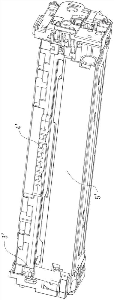
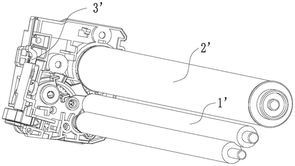
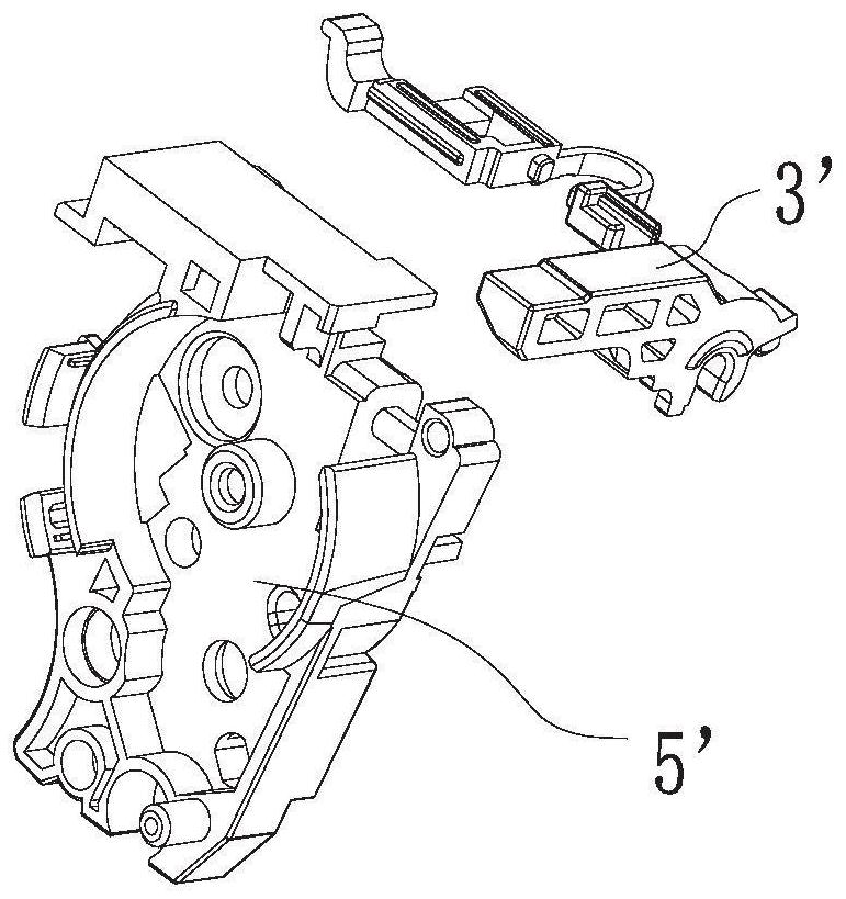
However, in the existing elastic parts, in order to avoid installation of the processing box on the imaging device, the stressed part of the elastic part is designed with a depression, the overall structure is complex, the reliability is poor, and it takes up a lot of space, which makes the limited space of the processing box even more cramped and inconvenient. Processing and assembly, especially during assembly, often cause unnecessary interference, which brings a lot of inconvenience to the assembly process

Method used


Image

  • Stirring structure for processing box and processing box thereof
  • Stirring structure for processing box and processing box thereof
  • Stirring structure for processing box and processing box thereof

Examples


Embodiment Construction

[0031] The following will clearly and completely describe the technical solutions in the embodiments of the present invention in conjunction with the accompanying drawings in the embodiments of the present invention. Features can be combined with each other. Apparently, the described embodiments are only some of the embodiments of the present invention, but not all of them. Based on the embodiments of the present invention, all other embodiments obtained by persons of ordinary skill in the art without making creative efforts belong to the protection scope of the present invention.

[0032] In the description of the present invention, it should be noted that unless otherwise specified and limited, the terms "installation", "connection" and "connection" should be understood in a broad sense, for example, it can be a fixed connection or a detachable connection. Connected, or integrally connected; it can be mechanically connected or electrically connected; it can be directly conn...


PUM


Abstract

The shifting structure is applied to clutch control of a photosensitive drum and a developing roller and comprises the photosensitive drum, a drum frame, the developing roller, a developing frame and a force receiving component, and the developing frame is rotationally supported relative to the drum frame by taking a rotating axis on the developing frame as an axis; the developing frame moves between a contact position and a separation position relative to the drum frame, the developing roller is in contact with the photosensitive drum at the contact position, and the developing roller is separated from the photosensitive drum at the separation position; the force receiving component is used for receiving driving force from a driving head of the imaging equipment, the force receiving component is provided with a power receiving swing head with a backward pitching deflection receding position and a forward pitching deflection receding position, and the force receiving component is configured to move between a standby position and an operation position; when the force receiving member is at the operation position and force is applied to the power receiving swing head of the force receiving member, the developing roller can move so that the developing roller is at the separation position; the processing box is small in size, simple in structure and convenient to disassemble and assemble.

Description

【Technical field】 [0001] The invention relates to the technical field of printers, in particular to a toggle structure for a process box and the process box. 【Background technique】 [0002] A process cartridge is a consumable in an electrophotographic imaging device or a printer. It can be detachably installed in an imaging device. It usually includes a drum frame for accommodating a photosensitive drum, a developing frame for accommodating a developer, a developing roller, and a powder feeding roller. The developing frame supports A rotatable developer roller that delivers developer to the developer roller via a powder feed roller. During the working process, the process cartridge receives the driving force from the imaging device, and transmits the driving force to the photosensitive drum, developing roller and powder feeding roller through the gear set. [0003] In the prior art, as the Chinese Patent Publication No. CN102193476B discloses a process box, such as Figure ...

Claims


Application Information

Patent Timeline
IPC IPC(8): G03G21/18G03G21/16
CPCG03G21/186G03G21/1619G03G21/1676G03G21/1671
Inventor 李军伟
Owner ZHUHAI CHINAMATE TECH
Learn More