
Touch screen

A technology of touch screen and touch layer, which is applied in the direction of instruments, computing, electrical digital data processing, etc. It can solve the problems of affecting visual sensory experience, increasing breakpoint static electricity, ESD damage, etc., achieves good antistatic effect and reduces static electricity intensity Effect

Pending Publication Date: 2022-05-13
CHONGQING LAIBAO TECH
View PDF0 Cites 0 Cited by
  • Summary
  • Abstract
  • Description
  • Claims
  • Application Information

AI Technical Summary

Problems solved by technology

[0003] Since the metal grid touch screen is made of very fine metal wires to form a metal grid structure, X-direction electrodes or Y-direction electrodes are formed by designing breakpoints. Since the metal wire width is usually less than 5um and is very thin, a single metal wire is antistatic ( ESD) ability is weak, and because the insulating layer between the two layers of electrodes is very thin, it is easy to form a discharge between the channel metal line of one layer and the optical matching metal line of the other layer, and ESD damage occurs, making the middle isolation The insulating layer is broken down, and a short circuit or open circuit occurs between the two layers, which affects the normal function of the touch screen (TP).
[0004] In order to improve the signal channel metal line, it is often necessary to design enough breakpoints on the optical matching metal line to disperse static electricity to the optical matching metal line to protect the signal channel metal line. Due to the increase in the number of breakpoints, the metal grid touch screen will The visual difference in different areas increases, which affects the visual sensory experience. Sometimes increasing the breakpoint will still cause bad static electricity.

Method used


Image

  • Touch screen
  • Touch screen
  • Touch screen

Examples


Embodiment Construction

[0025] In order to illustrate the touch screen provided by the present application, the following will be elaborated in detail in conjunction with the drawings of the specification and the text descriptions of the embodiments.

[0026] The present application provides a touch screen with a metal grid structure and good antistatic performance.

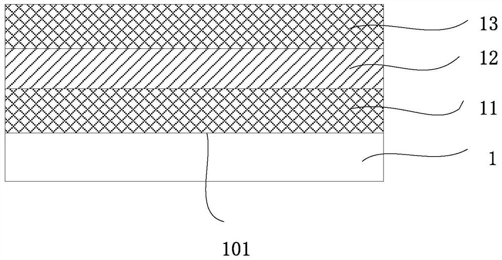
[0027] Such as figure 1 As shown, the touch screen provided by the embodiment of the present application includes a substrate 1 made of materials such as glass or film, and the substrate 1 has at least a first surface 101 . The touch screen also includes a first touch layer 11 located on the first surface 101; an insulating layer 12 located on the first touch layer 11 and on a surface away from the first surface 101; On the insulating layer 12 , the second touch layer 13 is on a surface away from the first touch layer 11 .

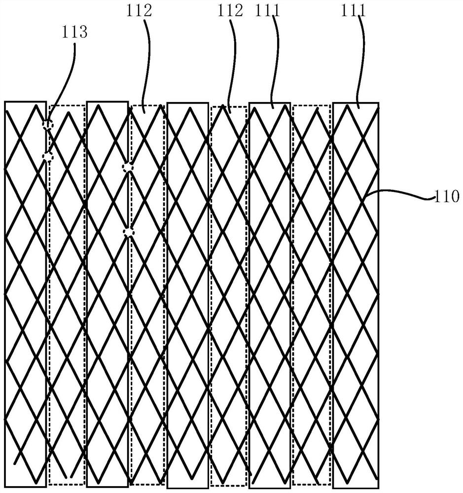
[0028] Such as figure 2 As shown, the first touch layer 11 includes a first grid block 111 and a second grid ...


PUM

PropertyMeasurementUnit
Line widthaaaaaaaaaa
Diameter lengthaaaaaaaaaa

Abstract

The invention relates to the field of touch screens, in particular to a touch screen. The touch screen comprises a substrate, the substrate is at least provided with a first surface, and the touch screen further comprises a first touch layer located on the first surface; the insulating layer is positioned on the first touch layer and is far away from the surface of one side of the first surface; and the second touch layer is positioned on the insulating layer and is far away from the surface of one side of the first touch layer. Each of the first touch layer and the second touch layer comprises a signal channel and an optical matching grid block, and when metal wires of the signal channels and the optical matching grid blocks of different touch layers are intersected, at least two fracture openings are formed near the intersection of the metal wires of the optical matching grid blocks; therefore, the touch screen has a good antistatic effect.

Description

technical field [0001] The present application relates to the field of flat panel display technology, in particular to the field of touch screens, and in particular to a touch screen. Background technique [0002] At present, the metal grid touch screen generally designs a two-layer metal grid structure, specifically designing a layer of X-direction electrodes and a layer of Y-direction electrodes. Match metal lines. The optical matching metal lines that are not connected to the signal channel are separated by designing breakpoints, and at the same time, the metal lines of the signal channel are divided into individual metal grid blocks that are connected to the signal. The signal channel metal lines of the electrodes in the X direction and the electrodes in the Y direction are electrically insulated by an insulating layer between the two layers of metal grid structures. [0003] Since the metal grid touch screen is made of very fine metal wires to form a metal grid struct...

Claims


Application Information

Patent Timeline
IPC IPC(8): G06F3/041
CPCG06F3/041
Inventor 杨高乐李平唐晟乐卫文胡洪涛朱贻祥
Owner CHONGQING LAIBAO TECH
Learn More