Concrete floor bearing capacity calculation method considering beam and plate interaction

A calculation method and concrete technology, applied in special data processing applications, constraint-based CAD, instruments, etc., can solve problems such as errors in research results and experimental results, and achieve reliable results, simple processes, and sufficient theoretical basis

Pending Publication Date: 2022-05-13
CHINA UNIV OF MINING & TECH +1
View PDF0 Cites 2 Cited by
  • Summary
  • Abstract
  • Description
  • Claims
  • Application Information

AI Technical Summary

Problems solved by technology

Although experts and scholars at home and abroad have never stopped researching on this theory, there are always some errors between the research results and the experimental results.

Method used


Image

  • Concrete floor bearing capacity calculation method considering beam and plate interaction
  • Concrete floor bearing capacity calculation method considering beam and plate interaction
  • Concrete floor bearing capacity calculation method considering beam and plate interaction

Examples


Embodiment 1

[0081] A method for calculating the bearing capacity of concrete floors considering the interaction between beams and slabs, the slabs include slabs and beams supporting the slabs, the slabs are rectangular slabs, specifically the rectangular slabs in this embodiment are two-way slabs, specifically The calculation steps are as follows:

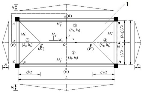
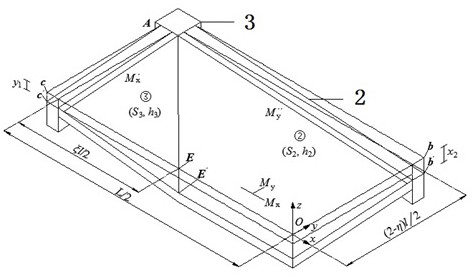
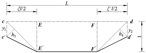
[0082] Step 1. Determine the yield line diagram of the floor under the condition of uniformly distributed load, considering the interaction of beams and slabs, assuming the position of the yield line and changing parameters.

[0083] Step 2, using the linear difference method to solve the yield line bending moment of each plate;

[0084] Step 3, determine the length, width and height parameters of the beam and the slab;

[0085] Step 4, calculate the negative bending moment ratio M' at the fixed boundary and the spring boundary according to the parameters and formulas in steps 1 to 3 1 / M 1 ;

[0086] Step 5, calculate the negative bending...

Embodiment 2

[0170] If the rectangular plate is a one-way plate, the x in Step 3 of Example 1 1 、x 2 、y 1 、y 2 , so that x 1 =x 2 = 1 or y 1 =y 2 =1, that is, the rectangular plate is a one-way plate, and other calculation steps are consistent with Embodiment 1.

Embodiment 3

[0172] Two sets of floor specimens (numbered S1 and S2 respectively) were selected to verify the accuracy and efficiency of this calculation method. The parameters of the specimens are: S1 and S2 both adopt the floor size of 4800mm×2300mm×70mm, and the beam section size of 100mm× 180mm, the cross-sectional size of the column is 200mm×200mm; S1 adopts double-layer two-way Reinforcement layout method, S2 adopts separate type Reinforcement arrangement: HRB400 is used for steel bars in slabs, beams and columns, the diameters of the steel bars are 6mm, 10mm and 12mm, the yield strengths are 424.6MPa, 417.0MPa, 415.8MPa, and the ultimate strengths are 605.9MPa, 565.0MPa, 553.2MPa, respectively. The diameter of the rib is 6mm. The specimen is C30 commercial concrete, the compressive strength of 28d cube is 30.9MPa, and the thickness of concrete protective layer is 15mm.

[0173] Table 2 and Table 3 give the calculated and test values ​​of the ultimate bearing capacity of S1 and S...


PUM


Abstract

The invention relates to the field of floor system ultimate load calculation methods, and discloses a concrete floor system bearing capacity calculation method considering beam and plate interaction, which considers the influence of torsional deformation and vertical deformation of a beam on floor system bearing capacity, quantifies the constraint effect of the beam on the plate, and is applied to a floor system ultimate bearing capacity calculation formula. The method has the advantages of sufficient theoretical basis, simple process and reliable result, the calculation result can meet the requirements of actual engineering, and the method has wide adaptability.

Description

technical field [0001] The invention relates to the field of calculating the ultimate load of slabs, in particular to a method for calculating the bearing capacity of concrete floors considering the interaction between beams and slabs. Background technique [0002] As an important load-bearing component of the structure, the floor's bearing capacity is of vital significance to the building, so the calculation method of the floor's bearing capacity is also very important. Although experts and scholars at home and abroad have never stopped researching on this theory, there are always some errors between the research results and the experimental results. [0003] When the beam is under different conditions of torsional deformation and vertical deformation, the bearing capacity of the floor will definitely be affected differently. Therefore, it is very necessary to establish a calculation method for the bearing capacity of the floor under the influence of beam-slab interaction....

Claims


Application Information

Patent Timeline
Patent Type & Authority Applications(China)
IPC IPC(8): G06F30/13G06F30/17G06F111/04G06F119/14
CPCG06F30/13G06F30/17G06F2111/04G06F2119/14
Inventor 王勇韩冠旭占德响刘素萍王功臣袁彬部翼翔任兆卿姜亚强陈振兴古傲林张连弟冯文会刘嘉文普为利马梦男王为为耿民腾
Owner CHINA UNIV OF MINING & TECH
Why Eureka
Try Eureka