Electromagnetic wind-induced galloping energy collection device

An energy harvesting, electromagnetic technology, applied in the field of electricity, can solve the problems of large internal impedance, low output power, low energy conversion efficiency, etc., to achieve the effect of small internal impedance, output power improvement, conversion efficiency and output power improvement

Pending Publication Date: 2022-05-13
BEIJING INSTITUTE OF TECHNOLOGYGY
View PDF1 Cites 0 Cited by
  • Summary
  • Abstract
  • Description
  • Claims
  • Application Information

AI Technical Summary

Problems solved by technology

[0006] In view of this, the present invention provides an electromagnetic wind-induced galloping energy harvesting device, which can solve the problems of large internal impedance (megohm level), low energy conversion efficiency and low output power of the piezoelectric wind-induced vibration energy harvesting structure

Method used


Image

  • Electromagnetic wind-induced galloping energy collection device
  • Electromagnetic wind-induced galloping energy collection device

Examples


Embodiment 1

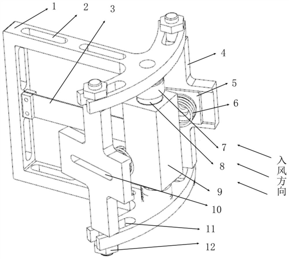
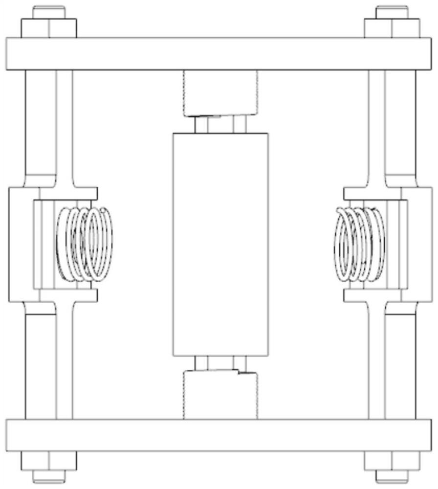
[0044] The present embodiment provides an electromagnetic wind-induced vibration energy harvesting device, the whole is a symmetrical frame structure, left and right and upper and lower symmetrical respectively; see attached Figure 1-2 The apparatus comprises: main frame 1, elastic vibration beam 3, limit adjustment stop 4, adjustable spring base 5, spring 6, coil 7, permanent magnet 8, resistive oscillator 9 and nut 12;

[0045] The main frame 1 is a symmetrical frame structure, formed by a U-shaped frame and two curved plates in one piece; the plane where the U-shaped frame is arranged in a vertical direction, and the opening of the U-shaped frame is horizontal; the two curved plates are formed in one piece at the end of the two side plates of the U-shaped frame, and the two curved plates are arranged in a horizontal direction, and the two curved plates are curved in the direction where the U-shaped frame is located; each end of the curved plate is processed with U-shaped groove...

Embodiment 2

[0059] On the basis of Example 1, the structure of the two coils 7 of the upper and lower symmetry in Example 1 is replaced by the structure of the two coils asymmetrically up and down or the structure of a single coil; at this time, the two upper and lower symmetrically arranged magnets 7 and the coil 7 are not necessarily coaxial, the asymmetrical arrangement of the two coils or the use of a single coil is only the output power is different.

Embodiment 3

[0061] In the present embodiment, on the basis of Example 1, the cross-sectional shape of the blocking oscillator 9 may also employ a rectangular or triangular non-streamlined left-right symmetrical shape; the cross-sectional shape of the permanent magnet 4 may also be square, triangular or other shapes.


PUM


Abstract

The invention discloses an electromagnetic wind-induced galloping energy collection device which comprises a main frame, an elastic vibration beam, a coil, a permanent magnet, a choked flow vibrator and an amplitude limiting assembly. One end of the elastic vibrating beam is fixed on the main frame, and the other end of the elastic vibrating beam is fixedly provided with a choked flow vibrator; wherein the plane where the elastic vibration beam is located is arranged in the vertical direction, and the length direction of the flow choking vibrator is arranged in the vertical direction; the coil is fixed on the main frame, the permanent magnet is fixed at the end part of the choked flow vibrator, and the coil and the permanent magnet are opposite to each other but not in contact with each other; the two amplitude limiting assemblies are installed on the main frame and located on the two sides of the flow blocking vibrator respectively, and the amplitude limiting assemblies are used for limiting the amplitude of the flow blocking vibrator when the flow blocking vibrator does left-right reciprocating periodic motion. According to the invention, the problems of large internal impedance (megohm level), low energy conversion efficiency and small output power of a piezoelectric wind-induced vibration energy harvesting structure can be solved.

Description

Technical field [0001] The present invention belongs to the field of electrical technology, specifically relates to an electromagnetic wind-induced vibration energy harvesting device. Background [0002] With the rapid development of modern information technology, the demand for information and timeliness put forward higher and higher requirements, in order to meet the needs of information collection, the distribution and application of wireless sensor networks have become more and more extensive. The question that arises is how to provide effective and stable long-term power supply to these wireless sensing networks. Traditional chemical batteries have limited use time due to their storage capacity limitations and must be replaced regularly, unable to meet the current needs of "setting and forgetting". In view of this problem, the commonly used solution is to collect and utilize the energy in the environment through different energy conversion methods, of which wind energy, as ...

Claims


Application Information

Patent Timeline
Patent Type & Authority Applications(China)
IPC IPC(8): H02K35/02H02K1/34
CPCH02K35/02H02K1/34
Inventor 熊雷高世桥金磊郭胜凯杜学达
Owner BEIJING INSTITUTE OF TECHNOLOGYGY
Why Eureka
Try Eureka