Torque coupling compensation control method based on segmented motor
A compensation control and motor control technology, applied in multiple motor speed/torque control, motor generator control, AC motor control and other directions, can solve problems such as poor torque synchronization, improve smooth running ability and tracking accuracy, reduce The effect of motor output torque mismatch
- Summary
- Abstract
- Description
- Claims
- Application Information
AI Technical Summary
Problems solved by technology
Method used
Image

Examples
Embodiment Construction
[0026] The torque coupling compensation control method based on the segmented motor of the present invention will be further described in detail below in conjunction with the drawings and embodiments.
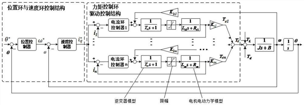
[0027] The permanent magnet synchronous segmented motors will jointly drive an inertial load (that is, a large-aperture telescope) to rotate. The permanent magnet synchronous segmental motor includes n-segment segmental motors, n is an integer greater than 2, and the stators of the n-segment segmental motors are arranged sequentially along a circle, that is, the n-segment segmental motors form a circular structure, etc. They form a ring-shaped integral stator, which has the same permanent magnet rotor, and the rotor drives the inertial load to move.
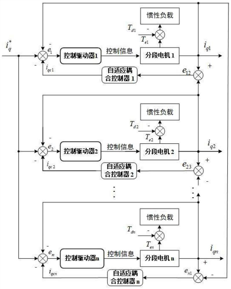
[0028] The closed-loop structure of the existing segmented motor motion control system is as follows: figure 1 As shown, the entire inertial motion system (the inertial motion system includes permanent magnet synchronous segmente...
PUM
 Abstract
Description
Claims
Application Information
PatSnap Eureka turns technology decisions into work you can execute. Powered by our Innovation Knowledge Graph, it runs expert workflows across engineering, life sciences, materials and intellectual property. Get your review-ready output in minutes.


