Ear protection device for medical imaging

A technology of medical imaging, ear, applied in the direction of medical science, ear therapy, measuring device, etc., which can solve the problem of lack of correct attenuation level, unawareness, high noise level of patients, etc.

Pending Publication Date: 2022-05-13
KONINKLJIJKE PHILIPS NV
View PDF0 Cites 0 Cited by
  • Summary
  • Abstract
  • Description
  • Claims
  • Application Information

AI Technical Summary

Problems solved by technology

This causes a common problem in MR as most patients are not used to wearing ear protection
Patients lack experience with correct attenuation levels, are unaware that they may be experiencing high noise levels, and do not have an objective measure of proper attenuation in the field
Therefore, instead of an objective measure of checking that earmuffs or eartips are being used correctly, a subjective check is sometimes performed in which the radiographer asks the patient during patient preparation if the device fits snugly

Method used


Image

  • Ear protection device for medical imaging
  • Ear protection device for medical imaging
  • Ear protection device for medical imaging

Examples


Embodiment Construction

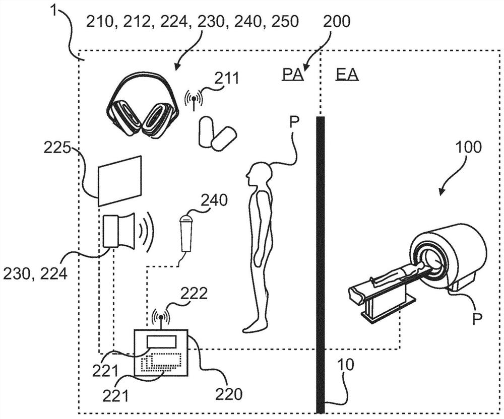
[0098] figure 1 A medical imaging system 1 is shown in a schematic block diagram, here the medical imaging system 1 is based on MR imaging.

[0099] The medical imaging system 1 is suitable for preparing and examining a patient P, and includes a medical imaging device 100 (for example, an MR imaging device) and an ear protection system 200 . It can be added that the ear protector system 200 can also be subsequently added to or integrated into an existing medical imaging system.

[0100] Such as figure 1 Depicted by the dashed line in , there may be a first position PR in which at least part of the ear protection system 200 is positioned and a second position ER in which the medical imaging device 100 is positioned. For example, the name PA may refer to the preparation area, while the name EA may refer to the inspection area. Likewise, the operation or use of the medical imaging system 1 and / or the medical imaging device 100 and / or the ear protection system 200 can be dist...


PUM


Abstract

The present disclosure relates to an ear protection system (200) for a medical imaging device. The ear protection system comprises: an ear protection device (210) adapted to be fitted around or in an ear of a patient (P) to be imaged and comprising at least a first communication interface (211) and at least one sensor device (212), the at least one sensor device is adapted to determine a measurement of noise passing through the ear protection device (210) towards the ear of the patient. The system (200) further comprises: a controllable signal transmitter (230) adapted to output a proxy signal representative of an expected imaging device noise and to be measured by the at least one sensor device (212); and a patient assistance device (220) adapted to assist the patient in fitting the ear protection device (210) and comprising at least a second communication interface. During a preparation phase of the patient prior to an imaging phase using the medical imaging device, the ear protection device (210) and the patient assistance device (220) are communicatively connected to each other via the first communication interface and the second communication interface, and the patient assistance device (220) generates assistance instructions for the patient based on an evaluation of the proxy signal and the measurement of the noise passing through the ear protection device (210) as determined by the sensor device (212).

Description

technical field [0001] The invention relates to an ear protection system for a medical imaging device, a medical imaging system, a method for ear protection in medical imaging, a computer program element and a computer readable medium. Background technique [0002] Patients undergoing magnetic resonance imaging (MRI) typically experience high sound pressure levels, averaging around 95-105 dB, which can increase to 130 dB or even higher for certain MR pulse sequences (Moelker A et al. Importance of Bone-Conducted Sound Transmission on Patient Hearing in the MR Scanner" (JMagn Reson Imag, 2005, Vol. 22, pp. 163-169)). Therefore, it is mandatory to wear ear protection during MR examinations, and different kinds of ear protection are used, the main ones being in the form of earmuffs and in-ear foam plugs, such as image 3 shown. Earmuffs are more widely used because they are easier and quicker to use and also because earplugs are inconvenient for many patients and may not be us...

Claims


Application Information

Patent Timeline
IPC IPC(8): A61F11/14A61F11/08A61B5/055
CPCA61F11/14A61F11/08A61B5/055G01R33/288G01R33/283A61F11/145
Inventor S·魏斯M·T·约翰逊
Owner KONINKLJIJKE PHILIPS NV
Why Eureka
Try Eureka