Preventing microbial growth in heat exchangers

A technology of heat exchangers and microorganisms, applied in the direction of heat exchange equipment, indirect heat exchangers, heat exchanger types, etc., can solve the problems of increased production costs and reduced efficiency

Pending Publication Date: 2022-05-13
EPFF ELECTRICAL PIPE FOR FLUID TRANSPORT
View PDF0 Cites 0 Cited by
  • Summary
  • Abstract
  • Description
  • Claims
  • Application Information

AI Technical Summary

Problems solved by technology

Often, production must be interrupted for cleaning, and chemicals are often used in cleaning, resulting in reduced efficiency and increased production costs

Method used


Image

  • Preventing microbial growth in heat exchangers
  • Preventing microbial growth in heat exchangers
  • Preventing microbial growth in heat exchangers

Examples


Embodiment Construction

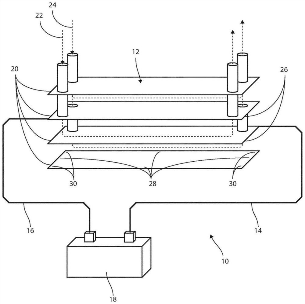
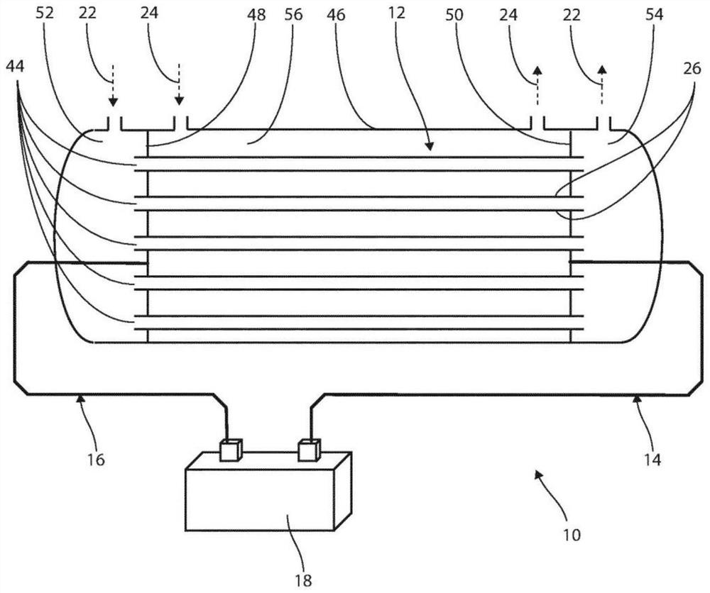
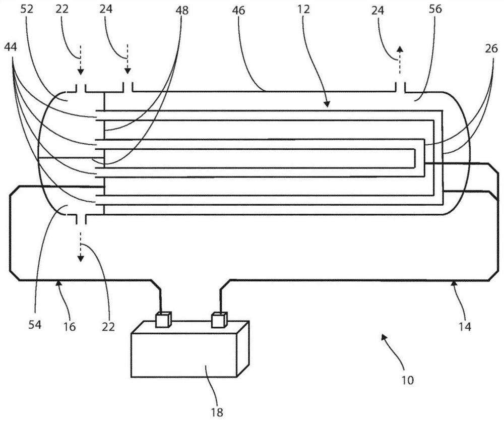
[0057] An embodiment of a heat exchanger assembly 10 is schematically shown in figure 1 middle. It consists of a heat exchanger 12 , a first electrical connector 14 , a second electrical connector 16 and a power source 18 . The heat exchanger 14 is a plate heat exchanger with four parallel plates 20 . The plates are rectangular and stainless steel. This means that each panel 20 has four sides 28 and four corners 3, as figure 1 shown.

[0058] The plates 20 are joined at edges (not shown) and form three channels in which the first fluid 22 and the second fluid 24 pass as figure 1 The flow indicated by the dotted line in . The first fluid 22 is sea water and the second fluid 24 is fresh water. The flow of the first fluid 22 and the second fluid 24 is created or provided by a pump (not shown). The flow direction of the first fluid 22 and the second fluid 24 is determined by figure 1 Indicated by arrows in , which show parallel flow. In alternative embodiments, the flow m...


PUM


Abstract

A heat exchanger assembly (10) is presented comprising a heat exchanger (12) forming one or more electrically connected partitions (26) separating a first fluid (22) and a second fluid (24). The assembly (10) also includes a first electrical connector (14) and a second electrical connector (16) operably connected to the bulkhead (26) of the heat exchanger (12), and a power source (18) operably connected to the first electrical connector (14) and the second electrical connector (16). The power source (18) is configured to supply electrical current to the one or more bulkheads (26) of the heat exchanger (12) through the first electrical connector (14) and the second electrical connector (16).

Description

technical field [0001] The proposed technology generally relates to the field of heat exchangers. It particularly concerns plate heat exchangers and heat exchangers in marine applications. The technique also involves preventing the growth of microorganisms on the interior surfaces of the heat exchanger. Background technique [0002] A heat exchanger is a system used to transfer heat between two or more fluids. Typically, fluids are separated by solid partitions to prevent mixing. Heat exchangers are used in both cooling and heating processes. [0003] Microbial growth in heat exchangers is a recognized problem. This increase can have a negative impact on the performance of the heat exchanger eg with regard to flow and thermal conductance. Microbial growth is particularly problematic in marine applications where seawater is supplied to heat exchangers. The nutrient content of seawater can be high, and the temperature of the seawater supplied is usually in a range conduc...

Claims


Application Information

Patent Timeline
Patent Type & Authority Applications(China)
IPC IPC(8): F28F13/16F28F19/00A23L3/16
CPCF28F13/16F28F19/004A23L3/16A61L2/03F28F2265/20F28D7/16
Inventor T·安德森
Owner EPFF ELECTRICAL PIPE FOR FLUID TRANSPORT
Why Eureka
Try Eureka