Automatic cutting equipment for steel wire rope

A technology for steel wire rope and equipment, applied in the field of automatic cutting equipment for steel wire rope, can solve problems such as low efficiency, easy uneven incision, etc., and achieve the effects of improving quality, good adaptability and shortening process flow

Pending Publication Date: 2022-05-17
南通市宇翔特种钢丝钢绳有限公司
0 Cites 0 Cited by

AI-Extracted Technical Summary

Problems solved by technology

[0004] In view of this, the present invention provides an automatic cutting equipment for steel wire ropes, which is used to solve the defects in...

Method used

The automatic cutting equipment of this steel wire rope, the steel wire weaving product is transported in the installation box by the conveying device, and the steel wire weaving product of the working end is fixedly clamped by the stripping device, and simultaneously, the steel wire weaving product is pulled back by the conveying device to make the steel wire weaving product Tension, and the tensioned steel wire braided product is fixed and clamped by the fixing device, and then, the position where the fixed and tensioned steel wire braided product needs to be cut is precisely rotated and cut by the rotary cutting device. The above process can effectively ensure that the steel wire The flatness of the incision after the weaving product is cut and cut improves the quality of the steel wire weaving product and shortens the process flow;
The steel wire weaving product of different diameters can be adaptively cut and processed by the cutting adjustment device in the rotary cutting device, so that the automatic cutting equipment has better adaptability;
The working principle of the present invention is: the staff inserts one end of the steel wire weaving product that needs to be cut off into the conveying device 2, and then starts the conveying device 2 to transport the steel wire weaving product to the installation box 1, and the steel wire weaving product extends inwardly One end successively passes through the fixing device 3 and the rotating cutting device 4 to interfere with the worki...

Abstract

The invention provides automatic cutting equipment for a steel wire rope, and relates to the technical field of steel wire product machining. A mounting box; the conveying device is arranged at the input end of the mounting box, and the conveying device is fixedly connected with the mounting box; the fixing device is arranged at the output end of the conveying device, and the input end of the fixing device is fixedly connected with the output end of the conveying device; the rotary cutting device is arranged in the mounting box, the rotary cutting device is fixedly connected with the mounting box, and the input end of the rotary cutting device is opposite to the output end of the fixing device; the stripping device is arranged in the mounting box, the stripping device is fixed to the mounting box, and the working end of the stripping device is opposite to the output end of the rotary cutting device; and the input end of the collecting box is arranged under the stripping device, and the quality of products can be effectively guaranteed.

Application Domain

Electronic waste recycling

Technology Topic

Wire ropeIndustrial engineering +1

Image

  • Automatic cutting equipment for steel wire rope
  • Automatic cutting equipment for steel wire rope
  • Automatic cutting equipment for steel wire rope

Examples

  • Experimental program(1)

Example Embodiment

[0073] In order to make the objectives, technical solutions and advantages of the present invention clearer, the present invention will be further described in detail below with reference to specific embodiments and accompanying drawings.
[0074] It should be noted that, unless otherwise defined, the technical or scientific terms used in the embodiments of the present invention shall have the usual meanings understood by those with ordinary skill in the art to which the present disclosure belongs. As used in this disclosure, "first," "second," and similar terms do not denote any order, quantity, or importance, but are merely used to distinguish the various components. "Comprising" or "comprising" and similar words mean that the elements or things appearing before the word encompass the elements or things recited after the word and their equivalents, but do not exclude other elements or things. Words like "connected" or "connected" are not limited to physical or mechanical connections, but may include electrical connections, whether direct or indirect. "Up", "Down", "Left", "Right", etc. are only used to represent the relative positional relationship, and when the absolute position of the described object changes, the relative positional relationship may also change accordingly.
[0075] As a preferred embodiment of the present invention, the present invention provides an automatic cutting equipment for wire ropes, including:
[0076] installation box;
[0077] The conveying device is arranged at the input end of the installation box, and the conveying device is fixedly connected with the installation box;
[0078] The fixing device is arranged at the output end of the conveying device, and the input end of the fixing device is fixedly connected with the output end of the conveying device;
[0079] The rotary cutting device is arranged inside the installation box, the rotary cutting device is fixedly connected with the installation box, and the input end of the rotary cutting device is arranged opposite to the output end of the fixing device;
[0080] The stripping device is arranged inside the installation box, the stripping device is fixed with the installation box, and the working end of the stripping device is arranged opposite to the output end of the rotary cutting device;
[0081] The collection box, the input end of which is located just below the stripping device.
[0082] The automatic cutting equipment of the steel wire rope conveys the braided wire products into the installation box through the conveying device, and the stripping device fixes and clamps the braided steel wire products at the working end. And the tensioned steel wire woven product is fixed and clamped by the fixing device, and then the rotary cutting device is used to perform precise rotary cutting on the position where the fixed tensioned steel wire woven product needs to be cut. The above process can effectively ensure the cutting of the steel wire woven product. The flatness of the incision after cutting improves the quality of the wire braided product and shortens the process flow;
[0083] Through the cutting adjustment device in the rotary cutting device, the wire braided products of different diameters can be cut adaptively, so that the automatic cutting equipment has better adaptability;
[0084] After cutting, the stripping device drives one end of the clamped and fixed steel wire braided product to move together, so that the two parts of the cut steel wire braided product that may still be bonded together are separated from each other, and the stripping device loosens one of the parts. The steel wire braided products of the section fall into the collection box, and the steel wire braided products are recovered. The recycling process is fully automatic, saving labor costs;
[0085] The conveying device pulls back the wire braided product to make the steel wire braided product taut, so that the incision produced in the subsequent cutting and cutting will be flat. The wire braided product is fixed and clamped, so that the subsequent cutting and cutting can be carried out smoothly and smoothly.
[0086] The preferred embodiments of the automatic cutting equipment for steel wire ropes of the present invention will be described below with reference to the accompanying drawings.
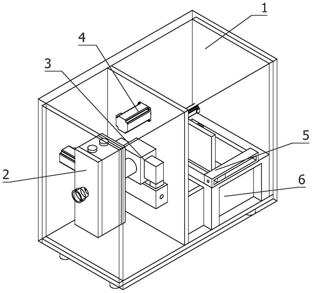
[0087] refer to figure 1 As shown, the present invention provides an automatic cutting equipment for steel wire ropes, the equipment includes;
[0088] installation box 1;
[0089] The conveying device 2 is arranged at the input end of the installation box 1, and the conveying device 2 is fixedly connected with the installation box 1;
[0090] The fixing device 3 is arranged at the output end of the conveying device 2, and the input end of the fixing device 3 is fixedly connected with the output end of the conveying device 2;
[0091] The rotary cutting device 4 is arranged inside the installation box 1, the rotary cutting device 4 is fixedly connected with the installation box 1, and the input end of the rotary cutting device 4 is arranged opposite to the output end of the fixing device 3;
[0092] The stripping device 5 is arranged inside the installation box 1, the stripping device 5 is fixed with the installation box 1, and the working end of the stripping device 5 is arranged opposite to the output end of the rotary cutting device 4;
[0093] The collection box 6, the input end of the collection box 6 is arranged just below the peeling device 5.
[0094] The working principle of the present invention is as follows: the staff inserts the end of the wire braided product that needs to be cut into the conveying device 2, and then starts the conveying device 2 to transport the wire braided product into the installation box 1, and the inwardly extending end of the wire braided product is passed through in turn. The over-fixing device 3 and the rotary cutting device 4 interfere with the working end of the stripping device 5 . The stripping device 5 fixes and holds the braided wire product at the working end, and the conveying device 2 pulls the braided wire product back to make the braided wire product taut. The fixing device 3 fixes and clamps the tensioned wire braided product. The rotary cutting device 4 performs precise rotary cutting on the position where the fixed and taut steel wire weaving product needs to be cut; after the cutting is completed, the stripping device 5 is activated. When the stripping device 5 is working, its working end moves horizontally to drive the clamped and fixed steel wire weaving. One end of the product moves together, so that the two sections of the cut wire braided product that may still be bonded are separated from each other, and at the same time, the stripping device 5 loosens one of the sections, and the wire braided product of this section falls into the collection box 6; the fixing device 3 Return to the original position, and the conveying device 2 conveys the stripped steel wire braided product out. Through the above process, the flatness of the incision after cutting and cutting of the steel wire knitted product can be effectively ensured, and the cutting adjustment device 4c in the rotary cutting device 4 can adaptively cut steel wire knitted products of different diameters, thereby improving the performance of the steel wire knitted product. quality and shorten the process flow.
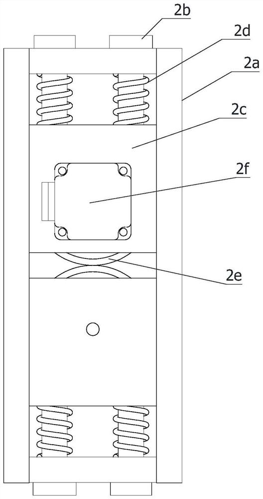
[0095] refer to image 3 As shown, the conveying device 2 comprises;
[0096] The first limit rail 2a is vertically arranged at the input end of the installation box 1, the first limit rail 2a is fixedly connected with the installation box 1, and the input end of the first limit rail 2a is arranged opposite to the input end of the installation box 1; The limit rod 2b is provided with several and symmetrically arranged at both ends of the first limit rail 2a, and the limit rod 2b is slidably connected with the first limit rail 2a; the installation block 2c is provided with several and symmetrically arranged at the first limit Inside the rail 2a, the mounting block 2c is fixedly connected with the limit rod 2b; the spring 2d is provided with several evenly distributed sleeves on the outside of the limit rod 2b, one end of the spring 2d collides with the first limit rail 2a, and the spring One end of the limit rail 2a is in conflict with the mounting block 2c; the conveying wheel 2e is provided with several and symmetrically distributed on the mounting block 2c, the conveying wheel 2e is rotatably connected with the mounting block 2c, and the outer side of the conveying wheel 2e is provided with an arc surface; A rotary driver 2f is arranged on the side of the mounting block 2c, the first rotary driver 2f is fixedly connected with the mounting block 2c, and the output end of the first rotary driver 2f is fixedly connected with the conveying wheel 2e.
[0097] The staff inserts the end of the wire braided product that needs to be cut between several conveying wheels 2e, and the conveying wheel 2e makes the conveying wheel 2e clamp and fix the steel wire braided product through the cooperation of the limit rod 2b and the spring 2d. Preferably, The first rotary driver 2f may be a servo motor, and the servo motor drives the conveying wheel 2e to rotate, and the conveying wheel 2e rotates and drives the wire braided product to be conveyed into the installation box 1 at the same time.
[0098] refer to Figure 4 As shown, the fixture 3 includes;
[0099] The guide tube 3a is horizontally arranged at the output end of the first limit rail 2a, the guide tube 3a is fixedly connected with the first limit rail 2a, and the guide tube 3a is communicated with the output end of the first limit rail 2a; the second limit rail 3b, arranged at the output end of the guide tube 3a, the second limit rail 3b is fixedly connected with the output end of the guide tube 3a, and the input end of the second limit rail 3b is communicated with the output end of the guide tube 3a; the clamping block 3c, There are several symmetrically arranged inside the second limit rail 3b, the clamping block 3c is interactively connected with the second limit rail 3b, and the clamping block 3c is provided with an arc-shaped clamping opening; On the side of the second limit rail 3b, the bidirectional screw slide table 3d is fixedly connected with the second limit rail 3b; the working end of the bidirectional screw slide table 3d is fixedly connected with the clamping block 3c.
[0100] The conveying device 2 conveys the braided steel wire products to the guide pipe 3a, the guide pipe 3a guides and conveys the braided steel wire products, the braided steel wire products pass through the second limit rail 3b and the rotary cutting device 4 in turn, and the braided steel wire products and the working end of the stripping device 5 In case of conflict, the stripping device 5 fixes and clamps the steel wire woven product at the working end, and the conveying device 2 pulls the steel wire woven product back to make the steel wire woven product taut, so that the incision produced in the subsequent cutting and cutting is smooth. The bidirectional screw slide table 3d drives the clamping blocks 3c to contract with each other, and the clamping blocks 3c fix and hold the tensioned steel wire braided product, so that the subsequent cutting and cutting can be carried out smoothly and smoothly.
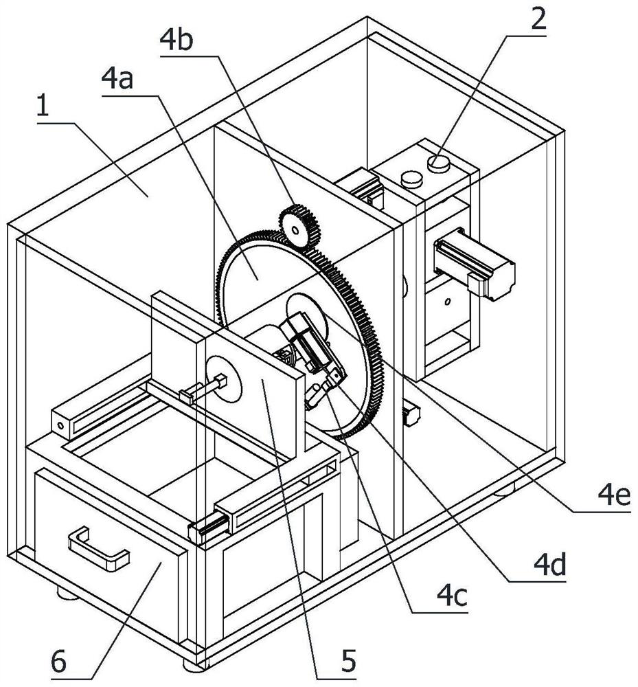
[0101] refer to figure 2 As shown, the rotary cutting device 4 includes;
[0102]The turntable 4a is arranged on the installation box 1, and the turntable 4a is rotatably connected with the installation box 1. The axis of the turntable 4a is provided with an opening, and the opening of the turntable 4a is arranged opposite to the output end of the second limit rail 3b; the rotary drive device 4b , is arranged on the installation box 1, the rotary drive device 4b is fixedly connected with the installation box 1, and the output end of the rotary drive device 4b is fixedly connected with the turntable 4a; the cutting adjustment device 4c is arranged on the turntable 4a, and the cutting adjustment device 4c is connected with the turntable 4a. Fixed connection, the second rotary driver 4d is arranged on the working end of the cutting adjustment device 4c, and the second rotary driver 4d is fixedly connected with the working end of the cutting adjustment device 4c; the cutting wheel 4e is arranged at the output end of the third rotary driver 4b2, The cutting wheel 4e is fixedly connected to the output end of the third rotary drive 4b2.
[0103] The above-mentioned stripping device 5 fixes and clamps the steel wire woven product at the working end, the conveying device 2 pulls the steel wire woven product back to make the steel wire woven product taut, and the fixing device 3 fixes and clamps the tensioned steel wire woven product. Start the rotary cutting device 4, preferably, the second rotary driver 4d is a servo motor, the second rotary driver 4d drives the cutting wheel 4e to rotate when working, and the cutting adjustment device 4c is responsible for driving the rotating cutting wheel 4e to move to the cutting position when it works, and rotates The driving device 4b drives the turntable 4a to rotate, and the turntable 4a drives the cutting wheel 4e to rotate together, and the cutting wheel 4e effectively cuts the wire woven product.
[0104] refer to Figure 5 As shown, in this embodiment, the rotary drive device 4b includes;
[0105] The driven ring gear 4b1 is sleeved on the turntable 4a, and the driven ring gear 4b1 is fixedly connected with the turntable 4a; the third rotary driver 4b2 is arranged on the installation box 1, and the third rotary driver 4b2 is fixedly connected with the installation box 1; The wheel 4b3 is arranged at the output end of the third rotary driver 4b2, the driving wheel 4b3 is fixedly connected with the output end of the third rotary driver 4b2, and the driving wheel 4b3 is engaged with the driven ring gear 4b1.
[0106] Preferably, the third rotary driver 4b2 can be a servo motor. When the third rotary driver 4b2 works, it drives the driving wheel 4b3 to rotate, the driving wheel 4b3 drives the driven ring gear 4b1 to rotate, and the driven ring gear 4b1 drives the turntable 4a to rotate.
[0107] refer to Figure 5 As shown, the cutting adjustment device 4c includes;
[0108] The installation shaft 4c1 is horizontally arranged on the turntable 4a, and one end of the installation shaft 4c1 is fixedly connected with the turntable 4a; the installation plate 4c2 is arranged on the second installation shaft 4c1, and the middle part of the installation plate 4c2 is rotatably connected with the second installation shaft 4c1; The linear driver 4c3 is arranged on the turntable 4a, and the non-working end of the first linear driver 4c3 is rotatably connected to the turntable 4a; the first connector 4c4 is arranged on the output end of the first linear driver 4c3, and one end of the first connector 4c4 It is fixedly connected with the output end of the first electric push rod, and one end of the first connector 4c4 away from the first linear driver 4c3 is rotatably connected with one end of the mounting plate 4c2.
[0109] Preferably, the first linear driver 4c3 can be an electric push rod. When the first linear driver 4c3 works, it pushes the first connector 4c4 to move, the first connector 4c4 pushes the mounting plate 4c2 to move, and the mounting plate 4c2 moves the second The rotary driver 4d and the cutting wheel 4e move together, and the moving position of the cutting blade can be effectively controlled by the first linear driver 4c3.
[0110] refer to Image 6 As shown, the peeling device 5 includes;
[0111] The bracket 5a is arranged inside the installation box 1, and the bracket 5a is fixedly connected with the installation box 1; the ball screw sliding table 5b is horizontally arranged on the bracket 5a, and the ball screw sliding table 5b is fixedly connected with the bracket 5a; the moving plate 5c, vertical It is directly arranged on the working end of the ball screw slide table 5b, and the moving plate 5c is fixedly connected with the working end of the ball screw slide table 5b; the clamping device 5d is horizontally arranged on the moving plate 5c, and the clamping device 5d is connected with the moving plate 5c. Fixed connection.
[0112] The conveying device 2 transports the wire braided product into the installation box 1, and the inwardly extending end of the wire braided product passes through the fixing device 3 and the rotary cutting device 4 in sequence and collides with the working end of the clamping device 5d, and the clamping device 5d compresses the wire braided. The product is clamped and fixed, and the conveying device 2 pulls back the wire braided product to tighten the wire braided product. The fixing device 3 fixes and clamps the tensioned wire braided product. The rotary cutting device 4 performs precise rotary cutting on the outer covering layer of the fixed and tensioned steel wire braided product. After the cutting is completed, the ball screw slide table 5b drives the moving plate 5c to move, and the moving plate 5c drives the clamping device 5d to move. The two sections of the braided product are separated from each other, and at the same time, the peeling device 5 loosens one of the sections, and the clamping device 5d loosens one of the sections. The steel wire braided product of this section falls into the collection box 6, and the recovery process is fully automatic, saving labor costs. .
[0113] refer to Figure 7 As shown, the clamping device 5d comprises;
[0114] The installation frame 5d1 is arranged on the movable plate 5c, and the installation frame 5d1 is fixedly connected with the movable plate 5c; the third limit rail 5d2 is provided with several and symmetrically arranged on the installation frame 5d1, and the third limit rail 5d2 is connected with the installation frame 5d1. Fixed connection; the slider 5d3 corresponds to the third limit rail 5d2 one-to-one, and is slidably connected to the corresponding third limit rail 5d2; the clamp 5d4 corresponds to the slider 5d3 one-to-one, and is slidably connected to the corresponding slider 5d3 5d3 is fixedly connected; the second linear driver 5d5 is arranged on the mounting frame 5d1, and the second linear driver 5d5 is fixedly connected to the mounting frame 5d1; the second connector 5d6 is arranged at the output end of the second linear driver 5d5, the second connector 5d6 is fixedly connected with the output end of the second linear driver 5d5; the connecting rod 5d7 is provided with several and symmetrically arranged on the second connecting head 5d6, one end of the connecting rod 5d7 is rotatably connected with the second connecting head 5d6, and the connecting rod 5d7 is connected with the second connecting head 5d6. The sliding blocks 5d3 are in one-to-one correspondence, and one end of the connecting rod 5d7 away from the second connecting head 5d6 is rotatably connected with the corresponding sliding block 5d3.
[0115] In this embodiment, the clamp 5d4 is provided with a plurality of "V"-shaped clamping jaws, and the clamping jaws are distributed in an array on the clamp 5d4.
[0116] Preferably, the second linear driver 5d5 can also be an electric push rod. The second linear driver 5d5 drives the second connecting head 5d6 to shrink and move, the second connecting head 5d6 drives the connecting rod 5d7 to shrink and move, and the connecting rod 5d7 drives the slider 5d3 to shrink and move. , the slider 5d3 drives the clamp 5d4 to shrink and clamp relatively.
[0117] Therefore, the device realizes the functions of the present invention through the following steps, thereby solving the technical problem proposed by the present invention;
[0118] Step 1. The staff inserts the end of the wire braided product that needs to be cut into the conveying device 2;
[0119] Step 2, the conveying device 2 transports the wire braided product into the installation box 1, and the inwardly extending end of the wire braided product collides with the working end of the stripping device 5 through the fixing device 3 and the rotary cutting device 4 in turn;
[0120] Step 3: The stripping device 5 fixes and holds the steel wire braided product at the working end, and the conveying device 2 pulls the steel wire braided product back to tighten the steel wire braided product;
[0121] Step 4. The fixing device 3 fixes and clamps the tensioned steel wire braided product;
[0122] Step 5. The rotary cutting device 4 performs precise rotary cutting on the position where the fixed tensioned steel wire braided product needs to be cut;
[0123] Step 6. After the cutting is completed, start the peeling device 5. When the peeling device 5 is working, its working end moves horizontally and drives one end of the clamped and fixed steel wire braided product to move together, so that the cut steel wire braided product that may still be bonded together. The two sections are separated from each other, and the stripping device 5 loosens one of the sections, and the wire braided product of this section falls into the collection box 6;
[0124] Step 7, the peeling device 5 loosens the outer covering of the woven wire product, and the outer covering of the wire woven product falls into the collection box 6;
[0125] Step 8: The fixing device 3 returns to its original position, and the conveying device 2 conveys the cut and switched steel wire braided products.
[0126] Those of ordinary skill in the art should understand that the discussion of any of the above embodiments is only exemplary, and is not intended to imply that the scope of the present disclosure (including the claims) is limited to these examples; under the spirit of the present invention, the above embodiments or There may also be combinations between technical features in different embodiments, steps may be carried out in any order, and there are many other variations of the different aspects of the invention as described above, which are not provided in detail for the sake of brevity.
[0127] Embodiments of the invention are intended to cover all such alternatives, modifications and variations that fall within the broad scope of the appended claims. Therefore, any omission, modification, equivalent replacement, improvement, etc. made within the spirit and principle of the present invention shall be included within the protection scope of the present invention.

PUM

no PUM

Description & Claims & Application Information

We can also present the details of the Description, Claims and Application information to help users get a comprehensive understanding of the technical details of the patent, such as background art, summary of invention, brief description of drawings, description of embodiments, and other original content. On the other hand, users can also determine the specific scope of protection of the technology through the list of claims; as well as understand the changes in the life cycle of the technology with the presentation of the patent timeline. Login to view more.

Similar technology patents

Multi-stitch flat type interlocking seam sewing machine

ActiveCN112877919AGuaranteed flatnessImprove quality and stability
Owner:东莞市志捷实业有限公司

Production method of aluminum alloy base material for 5052 alloy door plate

ActiveCN109487131AGuaranteed flatnessstable yield ratio
Owner:GUANGXI LIUZHOU YINHAI ALUMINUM IND

Ceramic shutter preparation device with homogenized surface nano coating

InactiveCN113333199AGuaranteed flatnessReduce hanging liquid phenomenon
Owner:赖花林

Band-shape communication optical cable

InactiveCN106383388AGuaranteed flatnessImprove optical path transmission efficiency
Owner:NANJING HAIYIN COMM EQUIP CO LTD

Cushion block for bench drilling machine

Owner:常熟顺发精工机械有限公司

Classification and recommendation of technical efficacy words

  • Guaranteed flatness
  • quality improvement

Full-automatic carton stacking production line

Owner:成都经纬机械制造有限公司

Rapid drying and disinfecting device for textile dyeing

PendingCN108677431AGuaranteed flatnessProtect the working environment
Owner:陈璐

Rice machining process

InactiveCN103691508Aquality improvementReduce broken rice rate
Owner:聂俊
Why Eureka
Try Eureka