Eureka AIR delivers breakthrough ideas for toughest innovation challenges, trusted by R&D personnel around the world.

Automatic clamping mechanism for piston pin hole machining

A clamping mechanism and piston pin hole technology, applied in metal processing machinery parts, metal processing equipment, clamping and other directions, can solve the problems of inability to achieve accurate alignment, low precision, and high rejection rate

Pending Publication Date: 2022-05-17
SICHUAN DANFU ENVIRONMENT TECH CO LTD
View PDF0 Cites 0 Cited by
  • Summary
  • Abstract
  • Description
  • Claims
  • Application Information

AI Technical Summary

Problems solved by technology

[0003] At present, there are electronic and mechanical methods for aligning the piston pin hole. After the piston is aligned, the piston components are transported to the clamping mechanism through the jaws and other transportation devices for clamping. However, due to the current alignment method The accuracy is not high, it can only guarantee the approximate position of the installation cavity, and cannot achieve accurate alignment. If the clamping is performed directly, the installation position of the piston will be wrong, which will affect the alignment between the processed pin hole and the installation cavity of the piston. Vertical, high scrap rate

Method used


Image

  • Automatic clamping mechanism for piston pin hole machining
  • Automatic clamping mechanism for piston pin hole machining

Examples


Embodiment Construction

[0029] The following will clearly and completely describe the technical solutions in the embodiments of the present invention with reference to the accompanying drawings in the embodiments of the present invention. Obviously, the described embodiments are only some, not all, embodiments of the present invention. Based on the embodiments of the present invention, all other embodiments obtained by persons of ordinary skill in the art without making creative efforts belong to the protection scope of the present invention.

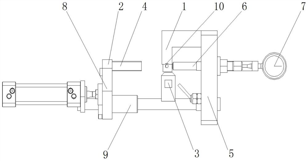
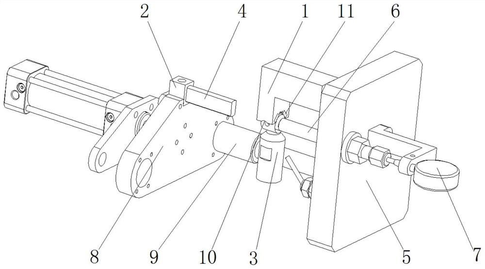
[0030] Such as Figure 1 to Figure 2 The shown automatic clamping mechanism for piston pin hole processing includes a V-shaped positioning block 1, a top material block 2 and a pressure material block 3, the central axis of the top material block 2 and the clamping of the V-shaped positioning block 1 The axes coincide, and the head of the ejector block 2 is provided with an elastic filler 4 that is compatible with the inner cavity of the piston. The initial an...


PUM


Abstract

The invention belongs to the technical field of piston machining, discloses an automatic clamping mechanism for piston pin hole machining, and mainly aims at solving the problem that the machining position error of a pin hole is too large due to the fact that an existing automatic clamping mechanism does not conduct accurate alignment before a piston is clamped. The mechanism comprises a V-shaped positioning block, a material ejecting block and a material pressing block, the central axis of the material ejecting block coincides with the clamping axis of the V-shaped positioning block, the head of the material ejecting block is provided with an elastic filler matched with an inner cavity of the piston, and the elastic filler can accurately align the angle of the piston through the elastic recovery effect of the elastic filler. The pin hole machining mechanism is simple and compact in overall structure, can play a good secondary accurate alignment role, can ensure that the vertical surface of the mounting cavity of the piston is perpendicular to the pin hole machining position after the piston is clamped, improves the product percent of pass, and saves the production cost.

Description

technical field [0001] The invention belongs to the technical field of piston processing, and mainly relates to an automatic clamping mechanism for processing piston pin holes. Background technique [0002] Today, pistons are widely used in engineering components such as engines, compressors, cylinders, and hydraulic cylinders. They have the functions of sealing, transmission, and pressure regulation. They have the advantages of good working performance and low manufacturing cost. When it comes to the piston, it has to be associated with the piston rod. Usually, the piston and the piston rod are connected by the piston pin, which requires processing the installation cavity and the pin hole for the head of the piston rod on the piston. In the process of piston processing, the pin hole is generally processed after milling the mounting cavity; at the same time, in order to ensure the stable connection between the piston and the piston rod and the working stability of the piston...

Claims


Application Information

Patent Timeline
Patent Type & Authority Applications(China)
IPC IPC(8): B23Q3/06B23Q3/18B23Q17/00
CPCB23Q3/06B23Q3/186B23Q17/003Y02P70/10
Inventor 王东舒向东
Owner SICHUAN DANFU ENVIRONMENT TECH CO LTD
Why Eureka
Eureka Blog
Learn More