Dual-purpose electric transfer trolley for erecting wind power blade web and transferring main beam

A dual-purpose electric technology for wind turbine blades, which is applied in the field of dual-purpose electric transfer vehicles for wind turbine blade web vertical placement and main girder transfer, which can solve the problem that the transfer vehicle cannot effectively exert the overall efficiency of the equipment, the high cost of forklift maintenance and repair, and the unfavorable company Business development and other issues, to achieve the effect of improving the limitation of site power requirements, improving the efficiency of transshipment operations, and avoiding flanging damage

Pending Publication Date: 2022-05-17
SINOMATECH JIUQUAN WIND POWER BLADE CO LTD
View PDF0 Cites 0 Cited by
  • Summary
  • Abstract
  • Description
  • Claims
  • Application Information

AI Technical Summary

Problems solved by technology

At present, most wind power blade manufacturing enterprises are designed with the largest blade shape of 60 meters and small blade design. After the mold is placed, there is no web storage and web assembly tooling location, resulting in poor production processes. At this stage, the web assembly tooling is installed Next to the web mold, the web is assembled and transferred vertically. The current web vertical transfer vehicle is a single-function transfer, which can only transfer the web, and the current transfer provides power for the forklift to transfer. It requires 2 people and 2 vehicles to cooperate at the same time. It is time-consuming and labor-intensive to complete the transfer. The transfer vehicle cannot effectively exert its comprehensive equipment efficiency, which is not conducive to the company's business development. The transfer of the model web and the main beam requires the use of forklifts as power, and the maintenance and repair costs of forklifts are relatively high.

Method used


Image

  • Dual-purpose electric transfer trolley for erecting wind power blade web and transferring main beam
  • Dual-purpose electric transfer trolley for erecting wind power blade web and transferring main beam
  • Dual-purpose electric transfer trolley for erecting wind power blade web and transferring main beam

Examples


Embodiment Construction

[0024] The present invention will be further described below in conjunction with the accompanying drawings.

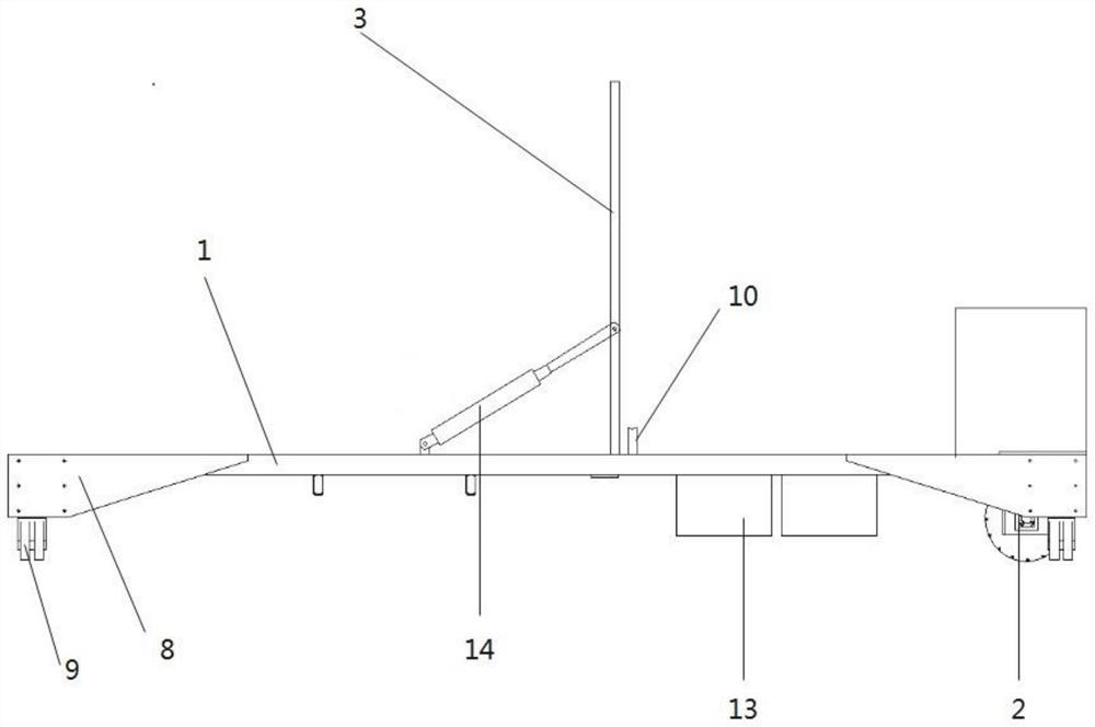
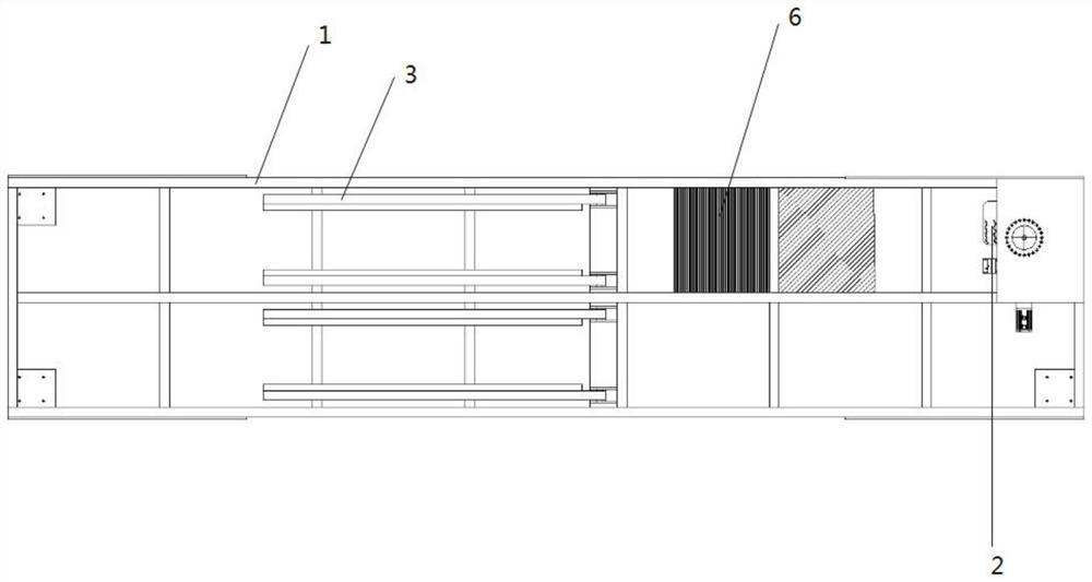
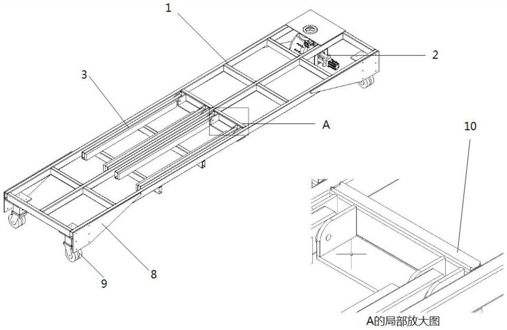
[0025] Such as figure 1 , 2 , 3 shows a dual-purpose electric transfer vehicle for wind power blade web vertical placement and main girder transfer, including a transfer vehicle frame 1, a drive system 2, a control system and a battery combination 6, and the drive system 2 and the control system are arranged on the transfer vehicle One end of the vehicle frame 1 is separately arranged on the upper and lower sides of the transfer vehicle frame 1, the battery assembly 6 is arranged under the transfer vehicle frame 1, and a wheel 9 is rotated under the other end of the transfer vehicle frame 1; the transfer vehicle Four web storage poles 3 are arranged on the frame 1 .

[0026] In order to realize the vertical transfer of wind power blade webs, the web storage struts 3 are arranged in the middle of the transfer vehicle frame 1 and distributed along the width direction o...


PUM


Abstract

The dual-purpose electric transfer trolley mainly comprises a transfer trolley frame, a driving system, a control system and a battery assembly, and the driving system and the control system are arranged at one end of the transfer trolley frame and arranged above and below the transfer trolley frame respectively. The battery combination is arranged below the transfer trolley frame, and wheels are rotationally arranged below the other end of the transfer trolley frame. According to the device, by arranging the web storage supporting rod and the hydraulic system, the current situation that time and labor are wasted when the wind power blade web is vertically placed and transferred is effectively solved, the transfer efficiency of the wind power blade web is improved, and the dual-purpose function of transferring the wind power blade web and a main beam through the transfer trolley is achieved; by arranging the battery combination, the defect that power needs to be provided by a forklift for transferring the wind power blade web is overcome, the walking range limitation of a transfer trolley is improved, the working efficiency of the wind power blade transfer tool is improved, and the transfer cost is reduced.

Description

technical field [0001] The invention belongs to the field of wind power blade transfer tooling, and in particular relates to a dual-purpose electric transfer vehicle for wind power blade web vertical placement and main girder transfer. Background technique [0002] With the rapid development of the wind power market and the continuous improvement of wind power technology, the capacity of a single unit is getting larger and longer, and the blades are getting longer and longer. The current main wind turbines on the market are gradually changing from 2.XMW 141 / 150 models to 3.XMW The 155 model transitioned, and the blades gradually developed from 60 to 80 meters. According to the matching demand of main engine and blade products in the current market, models above 3MW are gradually becoming the mainstream of units in the next few years. At the same time, the start of the wind power subsidy policy in 2021 has also led to the development of the entire wind power market towards l...

Claims


Application Information

Patent Timeline
Patent Type & Authority Applications(China)
IPC IPC(8): B60P3/00B60P7/15B60L50/60
CPCB60P3/00B60P7/15B60L50/60Y02T10/70
Inventor 李兴东卢家骐许世颖胡晓萍
Owner SINOMATECH JIUQUAN WIND POWER BLADE CO LTD
Why Eureka
Try Eureka