Helical gear side reducer arrangement structure

A technology for arranging structures and helical gears, which is applied to gear transmissions, belts/chains/gears, transmissions, etc., to achieve the effects of improved load-carrying capacity, long meshing time, and large contact area

Pending Publication Date: 2022-05-17
SHAANXI HANDE AXLE CO LTD
View PDF0 Cites 0 Cited by
  • Summary
  • Abstract
  • Description
  • Claims
  • Application Information

AI Technical Summary

Problems solved by technology

[0003] The purpose of the present invention is to provide a low-noise wheel-side reducer and its arrangement structure, which changes the existing planetary gear train into a helical gear, and at the same time, in order to solve the problem of axial force, some matching parts are made change

Method used


Image

  • Helical gear side reducer arrangement structure
  • Helical gear side reducer arrangement structure
  • Helical gear side reducer arrangement structure

Examples


Embodiment 1

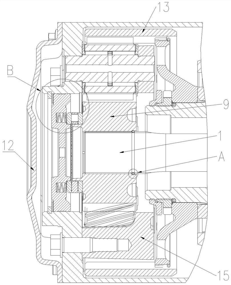
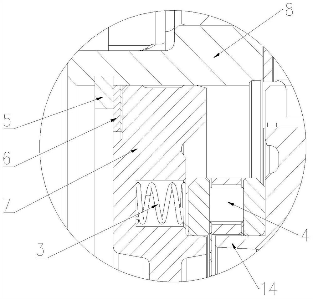
[0030] like figure 1 , 3 As shown in and 4, the arrangement structure of the helical gear side reducer includes a half shaft 1, a cross shaft 11, a ring gear 13, a sun gear 9 and a planetary gear 15, and one end of the half shaft 1 abuts against the cross shaft through a push pin 10 11. The other end of the axle shaft 1 is connected with a sun gear 9, the sun gear 9 is a helical gear, and the side of the sun gear 9 away from the cross shaft 11 is provided with a bearing seat 7, and the bearing seat 7 is close to one side of the sun gear 9. The side is connected with a thrust bearing 4, and the thrust bearing 4 abuts against the sun gear 9, and the planet gear 15 and the ring gear 13 are helical tooth structures, and the planet gear 15 meshes with the sun gear 9 and the ring gear 13 respectively.

[0031] The sun gear 9, the planetary gear 15 and the ring gear 13 are all designed as a helical tooth structure to make the meshing better. The meshing process between the helical t...

Embodiment 2

[0033] like Figure 1-4 As shown, the arrangement structure of the helical gear side reducer includes a half shaft 1, a cross shaft 11, a ring gear 13, a sun gear 9 and a planetary gear 15, and one end of the half shaft 1 abuts against the cross shaft 11 through a push pin 10, The other end of the half shaft 1 is connected with a sun gear 9, the sun gear 9 is a helical gear, the side of the sun gear 9 away from the cross shaft 11 is provided with a bearing seat 7, and the side of the bearing seat 7 close to the sun gear 9 is connected There is a thrust bearing 4, the thrust bearing 4 abuts against the sun gear 9, the planet gear 15 and the ring gear 13 are helical tooth structures, and the planet gear 15 meshes with the sun gear 9 and the ring gear 13.

[0034] The sun gear 9, the planetary gear 15 and the ring gear 13 are all designed as a helical tooth structure to make the meshing better. The meshing process between the helical tooth structures is an excessive process, and ...


PUM


Abstract

The arrangement structure comprises a half shaft, a cross shaft, a gear ring, a sun gear and a planet gear, one end of the half shaft abuts against the cross shaft through a lifting pin, the other end of the half shaft is connected with the sun gear, the sun gear is a bevel gear, a bearing seat is arranged on the side, away from the cross shaft, of the sun gear, and the planet gear is connected with the gear ring. The side, close to the sun gear, of the bearing seat is connected with a thrust bearing, the thrust bearing abuts against the sun gear, the planet gear and the gear ring are each of a helical tooth structure, and the planet gear is meshed with the sun gear and the gear ring. The sun gear, the planet gear and the gear ring are all designed to be of a helical tooth structure, so that the meshing performance is better, and generated noise is smaller.

Description

technical field [0001] The invention belongs to the field of wheel edge structures, and in particular relates to an arrangement structure of a helical gear edge reducer. Background technique [0002] Axle noise is a difficult problem for related companies, especially for some special customers, manufacturers who have special requirements for noise, require the axle noise to be reduced as much as possible. In order to achieve this purpose, the wheel reducer adopts a helical tooth structure to increase the gear overlap. There is an axial force in the helical gear, so there are new requirements for the layout of the wheel edge. Contents of the invention [0003] The purpose of the present invention is to provide a low-noise wheel-side reducer and its arrangement structure, which changes the existing planetary gear train into a helical gear, and at the same time, in order to solve the problem of axial force, some matching parts are made change. [0004] In order to solve th...

Claims


Application Information

Patent Timeline
Patent Type & Authority Applications(China)
IPC IPC(8): F16H1/28F16H57/08
CPCF16H1/28F16H57/08
Inventor 李静周群辉蔡明
Owner SHAANXI HANDE AXLE CO LTD
Why Eureka
Try Eureka