
Pulling plate structure of converter transformer

A technology of converter transformers and pull plates, which is applied in the field of transformers, can solve the problems of magnetic flux leakage in the pull plate structure and low structural strength, and achieve the effects of suppressing magnetic flux leakage, meeting lifting requirements, and facilitating hoisting and transportation

Pending Publication Date: 2022-05-17
GUANGDONG POWER GRID CO LTD +1
View PDF0 Cites 0 Cited by
  • Summary
  • Abstract
  • Description
  • Claims
  • Application Information

AI Technical Summary

Problems solved by technology

[0003] The purpose of the present invention is to provide a pull plate structure for a converter transformer to solve the problems of serious magnetic flux leakage and low structural strength of the pull plate structure

Method used


Image

  • Pulling plate structure of converter transformer
  • Pulling plate structure of converter transformer
  • Pulling plate structure of converter transformer

Examples


Embodiment 1

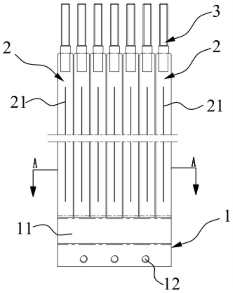
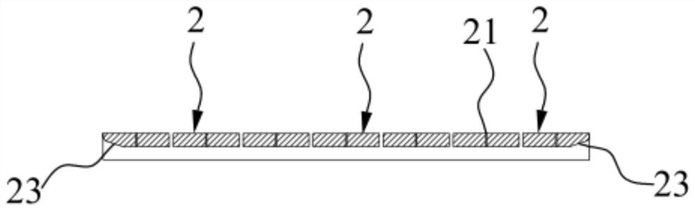
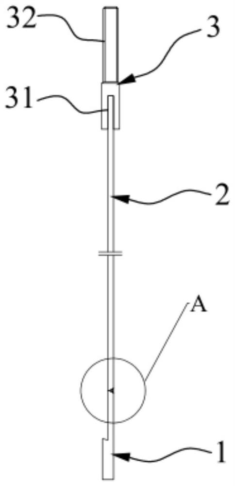
[0040] Such as Figure 1-Figure 12 As shown, the present invention provides a pull plate structure for a converter transformer, including a clamp plate 1 , a pull plate 2 and a lifting piece 3 . There are multiple pull plates 2, which are arranged at intervals along the length direction of the clamp plate 1 and are fixedly connected with the clamp plate 1. The pull plate 2 is provided with a magnetic flux leakage groove 21 along the length direction; the lifting part 3 is provided with multiple, A plurality of lifting parts 3 are fixedly connected with a plurality of pull plates 2 in one-to-one correspondence.

[0041] In this example, refer to the attached figure 1 , The pull plate structure of the converter transformer is composed of a clamp plate 1, seven pull plates 2 and seven lifting parts 3, each pull plate 2 is about 50mm wide, and the gap between two adjacent pull plates 2 is 2.5mm-3.5mm , preferably 3mm in the present embodiment, can effectively reduce the eddy cur...

Embodiment 2

[0048] The difference between this embodiment and Embodiment 1 is that the pull plate 2 in this embodiment is a high-strength low-magnetism steel plate. Specifically, 14MnMoNbB high-strength low-magnetic steel plate is used. The low-magnetic steel has no induction to ferromagnetism, has stable structure, excellent mechanical properties, low magnetic permeability and high resistivity. The drawing plate 2 is made of high-strength and low-magnetic steel plate, which can further reduce eddy current loss and further suppress the occurrence of magnetic flux leakage.


PUM


Abstract

The invention belongs to the technical field of transformers, and discloses a converter transformer pulling plate structure which comprises a clamping plate, a pulling plate and a hoisting piece. The multiple pulling plates are arranged at intervals in the length direction of the clamping plate and fixedly connected with the clamping plate, and magnetic leakage grooves are formed in the pulling plates in the length direction; the multiple hoisting pieces are fixedly connected with the multiple pulling plates in a one-to-one correspondence mode. According to the pull plate structure of the converter transformer, the magnetic flux leakage grooves are formed in the pull plates, magnetic flux leakage can be effectively restrained, the electrical performance requirement is met, the multiple pull plates are arranged in the length direction of the clamping plate at intervals and fixedly connected with the clamping plate, the hoisting pieces are fixedly installed at the tops of the pull plates, and hoisting and transportation are convenient. The pull plate structure of the converter transformer is simple in overall structure, convenient to operate and high in stability after being assembled, has very high mechanical strength and meets the hoisting requirement.

Description

technical field [0001] The invention relates to the technical field of transformers, in particular to a pull-plate structure of a converter transformer. Background technique [0002] With the development of UHV transmission technology, the capacity of a single converter transformer is increasing, and the weight of the converter transformer is also increasing. At the same time, according to the principle of electromagnetic induction, with the increase of the capacity and voltage regulation range of the converter transformer, When the alternating magnetic field generated by the current passes through the structural parts such as the stem pull plate and the silicon steel sheet, the magnetic flux leakage generated will become more and more concentrated, resulting in a high density of local eddy current loss, which may cause local overheating and other phenomena, thus affecting the safety of the product run. Contents of the invention [0003] The object of the present inventio...

Claims


Application Information

Patent Timeline
IPC IPC(8): H01F27/34H01F27/06
CPCH01F27/346H01F27/06
Inventor 王文洪吴轲潘维周继承
Owner GUANGDONG POWER GRID CO LTD
Learn More