Efficient surface mounting type permanent magnet synchronous motor structure with cooling structure

A technology of permanent magnet synchronous motor and cooling structure, applied to synchronous motor with static armature and rotating magnet, magnetic circuit shape/pattern/structure, magnetic circuit and other directions, can solve the problem of small air gap magnetic density and irreversible permanent magnet Problems such as demagnetization and large harmonics

Pending Publication Date: 2019-07-05
HARBIN UNIV OF SCI & TECH
View PDF0 Cites 0 Cited by
  • Summary
  • Abstract
  • Description
  • Claims
  • Application Information

AI Technical Summary

Problems solved by technology

[0003] The purpose of the present invention is to provide a high-efficiency surface-mounted permanent magnet synchronous motor structure with a cooling structure to solve the problem of large harmonics, small air gap flux density, large magnetic flux leakage between magnetic poles and temperature problems of the existing surface-mounted permanent magnet synchronous motor. Excessively high leads to problems such as irreversible demagnetization of permanent magnets

Method used


Image

  • Efficient surface mounting type permanent magnet synchronous motor structure with cooling structure
  • Efficient surface mounting type permanent magnet synchronous motor structure with cooling structure
  • Efficient surface mounting type permanent magnet synchronous motor structure with cooling structure

Examples


Embodiment Construction

[0009] In order to make the technical means, creative features, goals and effects of the present invention easy to understand, the present invention will be further described below in conjunction with specific embodiments.

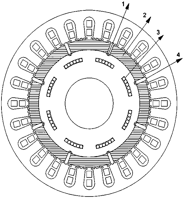
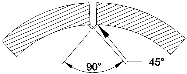
[0010] Such as figure 1 It is a structural schematic diagram of a high-efficiency surface-mounted permanent magnet synchronous motor with a cooling structure of the present invention; figure 2 It is a partial enlarged view of the magnetic bridge of a high-efficiency surface-mounted permanent magnet synchronous motor structure with a cooling structure in the present invention; it is characterized in that the motor adopts an inner rotor permanent magnet synchronous motor, and the internal structure of the stator and the rotor is improved; The above-mentioned stator teeth are added with 3 equidistant virtual slots on the original basis, and these virtual slots do not need windings; the surface of the rotor is a magnetic pole, and a 90° permanent magnet bridg...


PUM


Abstract

The invention provides an efficient surface mounting type permanent magnet synchronous motor structure with a cooling structure, and belongs to the technical field of motor structures. The motor adopts an inner rotor structure; a stator tooth is added with three equidistant virtual grooves; and the magnetic poles of the rotor is internally added with permanent magnet bridges; and grooves are formed below the magnetic poles. The technical key point is that the lowest frequency of cogging torque harmonic wave can be reduced through adding the virtual grooves on the stator tooth, so that the cogging torque amplitude is reduced; through adding the permanent magnet bridges in the rotor, the leakage flux between the magnetic poles can be effectively decreased, the gap flux density can be increased, the gap harmonic wave can be decreased, the fundamental wave content can be increased, gap waveforms with relatively good sine can be obtained, the harmonic wave distortion rate can be improved, remarkable effect is brought to restrict matrix pulsation, and higher stability is provided; and through forming the grooves below the permanent magnets to add water cooling channels, the permanent magnets on the rotor can be effectively prevented from too high temperature, and the closed magnetic circuits between the magnetic poles can be effectively decreased, so that the magnetic utilization rate is effectively improved.

Description

technical field [0001] The invention relates to the technical field of motors, in particular to a high-efficiency surface-mounted permanent magnet synchronous motor structure with a cooling structure. Background technique [0002] The surface-mounted permanent magnet synchronous motor is a motor that develops rapidly with the development of rare earth materials. Its stator adopts a cogged structure, and the rotor adopts a surface-mounted permanent magnet structure. The surface-mounted permanent magnet synchronous motor has the advantages of small size, simple structure, high efficiency, and high torque density. It is widely used in various engineering fields and is an energy-saving and environmentally friendly motor with great development potential. However, the excessive internal harmonics caused by the fluctuation of the tangential component force of the interaction between the permanent magnet and the armature teeth lead to the torque pulse ripple of the permanent magnet ...

Claims


Application Information

Patent Timeline
Patent Type & Authority Applications(China)
IPC IPC(8): H02K21/14H02K1/16H02K1/27H02K1/24H02K1/32
CPCH02K21/14H02K1/165H02K1/278H02K1/24H02K1/32H02K2213/03
Inventor 戈宝军匡恒王立坤
Owner HARBIN UNIV OF SCI & TECH
Why Eureka
Try Eureka