Processing technology of special-shaped coil

A processing technology and special-shaped coil technology, applied in coil manufacturing, instruments, measuring devices, etc., can solve problems such as loose air-core coils, failure to meet user's requirements for the shape of air-core coils, and failure to achieve bending effects, so as to prevent looseness and improve Pressing stability and molding effect, the effect of avoiding mutual interference

Pending Publication Date: 2022-05-17
浙江郎立电工器材有限公司
View PDF5 Cites 0 Cited by
  • Summary
  • Abstract
  • Description
  • Claims
  • Application Information

AI Technical Summary

Problems solved by technology

However, the current air-core coil is limited by the processing technology, resulting in its shape being a ring-shaped planar structure after winding and forming, which cannot meet the user's shape requirements for the air-core coil.
If the sheet-shaped air-core coil is directly pressed into an arc-shaped structure by a press brake, it will cause the air-core coil to loosen during the bending process, that is, the adjacent enameled wires in the coil are separated from each other and form several movable single coils , the desired bending effect cannot be achieved

Method used


Image

  • Processing technology of special-shaped coil
  • Processing technology of special-shaped coil
  • Processing technology of special-shaped coil

Examples


Embodiment 1

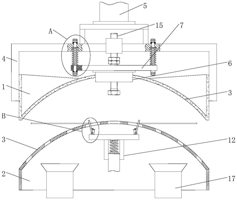
[0036] Example 1. A processing technology for special-shaped coils, comprising the following steps:

[0037] ① Use self-adhesive paint to paint the surface of the enameled wire to form a self-adhesive enameled wire. The self-adhesive paint layer is the existing self-adhesive paint with secondary bonding function. The self-adhesive paint can be heated after the hollow coil is wound. or energized for secondary bonding; then wind the self-adhesive enameled wire to form a hollow coil with a flat shape to obtain a hollow coil A;

[0038] ②Place the air-core coil A on the lower mold base to get the air-core coil B;

[0039] ③Heating or energizing the hollow coil, so that the self-adhesive paint on the surface of the B hollow coil is converted from a solid state to a molten state, and the C hollow coil is obtained;

[0040] ④The C hollow coil is pressed by the upper template, so that the C hollow coil changes from a flat shape to an arc shape curved along the thickness direction un...

Embodiment 2

[0054] Example 2. A processing technology for special-shaped coils, comprising the following steps:

[0055] ① Use self-adhesive paint to paint the surface of the enameled wire to form a self-adhesive enameled wire. The self-adhesive paint layer is the existing self-adhesive paint with secondary bonding function. The self-adhesive paint can be heated after the hollow coil is wound. or energized for secondary bonding; then wind the self-adhesive enameled wire to form a hollow coil with a flat shape to obtain a hollow coil A;

[0056] ②Place the air-core coil A on the lower mold base to get the air-core coil B;

[0057] ③Heating or energizing the hollow coil, so that the self-adhesive paint on the surface of the B hollow coil is converted from a solid state to a molten state, and the C hollow coil is obtained;

[0058] ④The C hollow coil is pressed by the upper template, so that the C hollow coil changes from a flat shape to an arc shape curved along the thickness direction un...


PUM


Abstract

The invention discloses a processing technology of a special-shaped coil, which comprises the following steps: firstly, painting the surface of an enameled wire by using self-adhesive paint to form a self-adhesive enameled wire, and then winding the self-adhesive enameled wire to form a hollow coil with a planar appearance; the hollow coil is placed on the lower die holder, the hollow coil is heated or electrified, the hollow coil C is pressed by the upper die plate, the hollow coil is changed into an arc shape from a plane shape under the mutual extrusion of the upper die plate and the lower die holder, and finally the hollow coil D is cooled to enable the self-adhesive paint to be cured again, so that the finished product hollow coil is obtained. The special-shaped hollow coil can be machined, and paint film damage and coil loosening in the machining process of the special-shaped hollow coil are prevented.

Description

technical field [0001] The invention relates to a special-shaped air-core coil, in particular to a processing technology of the special-shaped coil. Background technique [0002] With the improvement of the technical level, the demand for the shape of the hollow coil is gradually increasing; for example, for the flowmeter installed outside the water pipe, in order to reduce the overall shape of the flowmeter and improve its installation stability, it is necessary to design its own shape It is arc-shaped and closely attached to the outer wall of the cylindrical water pipe, which makes the hollow coil inside the flowmeter also need to be processed into an arc shape to adapt to the arc-shaped flowmeter housing. However, the current air-core coil is limited by the processing technology, resulting in its shape being a ring-shaped planar structure after winding and forming, which cannot meet the user's shape requirements for the air-core coil. If the sheet-shaped air-core coil is...

Claims


Application Information

Patent Timeline
Patent Type & Authority Applications(China)
IPC IPC(8): H01F41/071H01F41/077H01F41/06G01B21/08
CPCH01F41/071H01F41/077H01F41/06G01B21/08
Inventor 郎新利
Owner 浙江郎立电工器材有限公司
Why Eureka
Try Eureka