Defoaming device

A defoaming device and defoaming technology, which are applied in gas fuel, petroleum industry, fuel and other directions, can solve the problems of difficulty in determining the amount of defoaming agent added, inability to adapt to changes in bubbles, and poor foam elimination effect, so as to reduce production loss. , Improve the efficiency of adding, reduce the effect of usage

Active Publication Date: 2022-05-20
PETROCHINA CO LTD
View PDF5 Cites 0 Cited by
  • Summary
  • Abstract
  • Description
  • Claims
  • Application Information

AI Technical Summary

Problems solved by technology

[0004]However, since the addition amount of defoamer is not easy to determine, on the one hand, it leads to waste of defoamer, on the other hand, it cannot adapt to the working conditions of bubble changes, resulting in the loss of natural gas Poor effect on medium foam elimination

Method used


Image

  • Defoaming device
  • Defoaming device

Examples


Embodiment Construction

[0037] In order to make the purpose, technical solution and advantages of the present application clearer, the implementation manners of the present application will be further described in detail below in conjunction with the accompanying drawings.

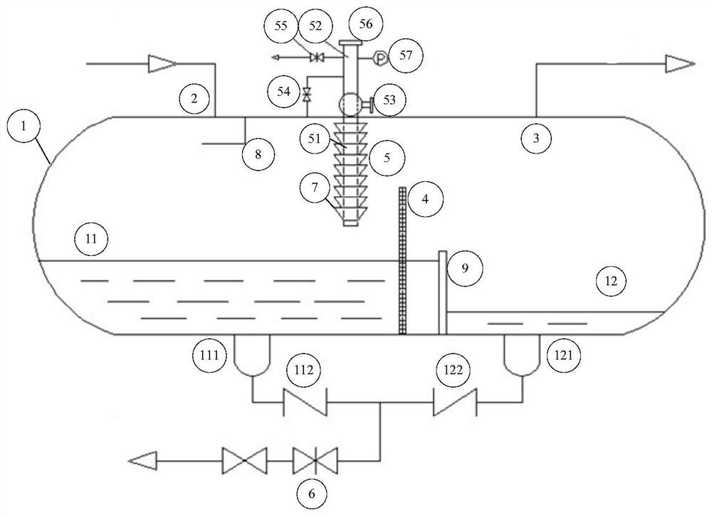
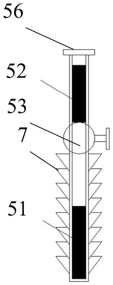
[0038] figure 1 It is a structural diagram of a defoaming device provided in the embodiment of this application, see figure 1 , The device includes: a separator cylinder 1, a gas inlet 2, a gas outlet 3, a defoaming screen 4, a defoaming cylinder 5 and a blowdown valve 6. The gas inlet 2 and the gas outlet 3 are respectively located on both sides of the top of the separator cylinder 1 . The defoaming screen 4 is vertically connected to the inner wall of the bottom of the separator cylinder 1, and the defoaming screen 4 is used for physically defoaming the contacted gas. The defoaming cylinder 5 passes through the top of the separator cylinder 1 and enters the interior of the separator cylinder 1. The defoaming cylinder 5 is loc...


PUM


Abstract

The invention discloses a defoaming device, and belongs to the field of natural gas production. According to the defoaming device provided by the embodiment of the invention, when the natural gas passes through the defoaming device, the defoaming rod in the defoaming cylinder can perform chemical defoaming on the natural gas, the defoaming wire mesh can perform physical defoaming on the natural gas, and through mutual cooperation of physical defoaming and chemical defoaming, the defoaming effect on the natural gas is improved. Besides, the defoaming rod is placed in the defoaming cylinder, and the defoaming rod is naturally consumed along with the amount of foam in the natural gas, so that the defoaming effect is ensured, the use amount of the defoaming rod is reduced, and the cost is reduced. Moreover, when the defoaming rods are consumed, the technicians can also quickly add the defoaming rods into the defoaming barrel without stopping production, so that the adding efficiency of the defoaming rods is improved, and the yield loss caused by stop production of the added defoaming rods is reduced.

Description

technical field [0001] The application relates to the field of natural gas production, in particular to a defoaming device. Background technique [0002] At present, in natural gas exploitation, due to the high gas velocity in the pipeline, the liquid precipitated in the general gas is difficult to form a stable continuous liquid phase in the pipeline, but is sandwiched in the gas phase in the form of tiny droplets. In the exploitation of shale gas, the sand-added volume fracturing technology is usually used to stimulate the reservoir. In order to effectively discharge residual fracturing flowback fluid, some well stations have adopted foam drainage and gas recovery technology. [0003] In related technologies, in order to eliminate the residual foam carried in natural gas, the method of pumping liquid defoaming agent into the system is mostly adopted. If the method of adding solid defoaming rods is often quantitatively added to the system intermittently. [0004] However,...

Claims


Application Information

Patent Timeline
Patent Type & Authority Applications(China)
IPC IPC(8): C10L3/10
CPCC10L3/101
Inventor 林宇计维安戴万能高晓根伍坤一
Owner PETROCHINA CO LTD
Why Eureka
Try Eureka