
Direct current transmission line fault detection method and system

A DC transmission line, fault detection technology, applied in fault location, information technology support system, detection of faults by conductor type, etc., can solve the problems of not considering capacitive current, slow protection speed, inability to identify, etc., to reduce the possibility of , the protection speed is fast, and the effect of improving the recognition degree

Active Publication Date: 2022-05-20
KUNMING UNIV OF SCI & TECH
View PDF9 Cites 0 Cited by
  • Summary
  • Abstract
  • Description
  • Claims
  • Application Information

AI Technical Summary

Problems solved by technology

Among them, the traveling wave protection is the main protection of the DC line, and its advantage is to determine the fault line quickly and accurately; the differential undervoltage protection is not only the main protection of the DC line, but also the backup protection of the traveling wave protection. For traveling wave protection, the protection speed is slow but the sensitivity and reliability are high, but the above two protections have the technical problem that the protection will malfunction in high-impedance faults, which has not been resolved.
Low voltage protection is the backup protection of traveling wave protection and differential undervoltage protection. This protection is divided into line low voltage protection and pole control line voltage protection. Its advantage is that high resistance faults that cannot be cut off by traveling wave protection and differential undervoltage protection , but there is a problem that it is impossible to distinguish what is an internal fault and what is an external fault
The longitudinal differential protection is the backup protection of the DC transmission line. Its advantage is that it can reliably cut off the high-resistance fault, but there is a problem that any voltage change may cause the protection to malfunction without considering the capacitive current.

Method used


Image

  • Direct current transmission line fault detection method and system
  • Direct current transmission line fault detection method and system
  • Direct current transmission line fault detection method and system

Examples


Embodiment 1

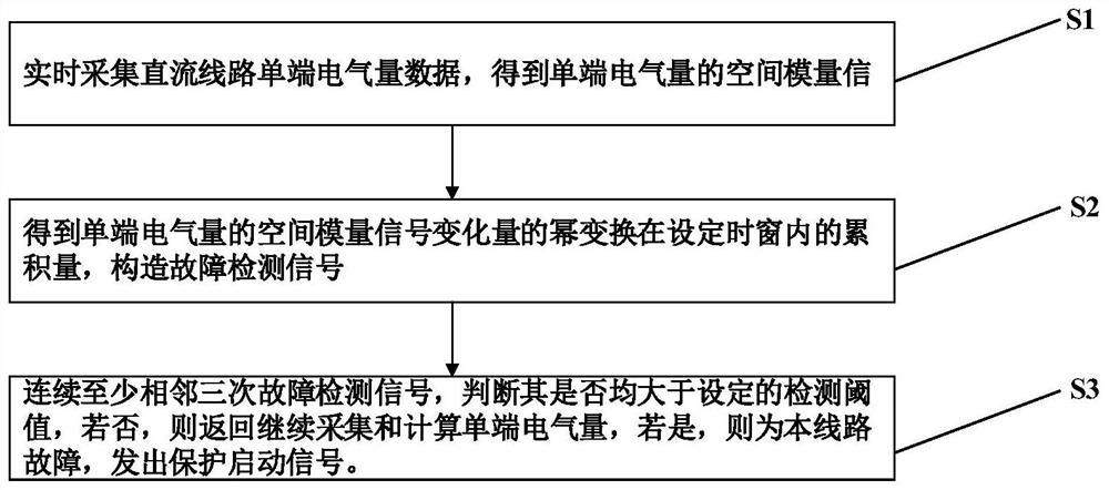
[0075] Embodiment 1: as figure 1 As shown, a single-pole grounding fault detection method in the case of long-distance high resistance of a direct current transmission line, the specific steps are:

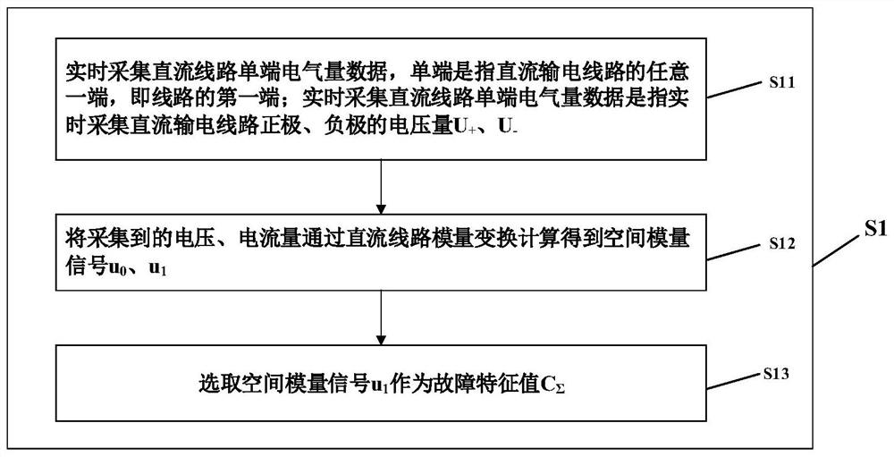
[0076] Step1: Collect the single-ended electrical quantity data of the DC line in real time, and obtain the space modulus signal of the single-ended electrical quantity, such as figure 2 As shown, the specific steps include:

[0077] Step1.1: Real-time collection of single-end electrical quantity data of the DC line. The single-end refers to any end of the DC transmission line, that is, the first end or the second end of the line. Real-time collection of DC line single-ended electrical quantity data refers to the real-time collection of the voltage and current U of the positive and negative poles of the DC transmission line + , U - ;

[0078] Step1.2: Calculate the collected voltage and current through the phase-mode transformation of the DC line to obtain the space modulus s...

Embodiment 2

[0126] Embodiment 2: A method for detecting a short-circuit fault between poles of a DC transmission line under a long-distance high-resistance fault, the specific steps are:

[0127] Step1: Collect the single-ended electrical quantity data of the DC line in real time, and obtain the space modulus signal of the single-ended electrical quantity. The specific steps include:

[0128] Step1.1: Real-time collection of single-ended electrical quantity data of DC lines, single-ended refers to any end of the DC transmission line, that is, the first or second end of the line; real-time collection of single-ended electrical quantity data of DC lines refers to real-time collection of DC The voltage and current U of the positive and negative poles of the transmission line + , U - ;

[0129] Step1.2: Calculate the collected voltage and current through the phase-mode transformation of the DC line to obtain the space modulus signal u + , u - ,, as shown in formula (1):

[0130]

[01...


PUM


Abstract

The invention relates to a direct current transmission line fault detection method and system, and belongs to the field of power system relay protection. The method comprises the following steps: firstly, collecting single-end electrical quantity data of a direct-current line in real time to obtain a spatial modulus signal of the single-end electrical quantity; calculating the cumulant of the power transformation of the space modulus signal variable quantity of the single-ended electrical quantity in a set time window, and constructing a fault detection signal; and continuously judging at least three adjacent fault detection signals, judging whether the fault detection signals are all greater than a set detection threshold value or not, if not, returning to continue to collect and calculate the single-end electrical quantity, and if yes, determining that the line has a fault, and sending out a protection starting signal. The invention also provides a DC line fault detection system. The method provided by the invention can quickly and reliably detect the line fault, and has the advantages of sensitivity, reliability and quickness.

Description

technical field [0001] The invention relates to a DC transmission line fault detection method and system, belonging to the field of relay protection of electric power systems. Background technique [0002] With the rapid development of my country's economy, AC transmission can no longer meet the electricity demand of our residents. Since my country's energy distribution and power load demand distribution are inversely phased, DC transmission lines have become the main direction of my country's power transmission development in the future due to their advantages such as large capacity, long transmission distance, and convenient grid interconnection. After the DC transmission line fails, the DC system will be blocked due to protection malfunction, which will lead to unnecessary outage of the DC transmission system. In addition, most of the DC lines are arranged in remote mountainous areas, where the natural environment is relatively harsh and maintenance is extremely inconven...

Claims


Application Information

Patent Timeline
Patent Type & Authority Applications(China)
IPC IPC(8): G01R31/08
CPCG01R31/085G01R31/088Y04S10/52
Inventor 束洪春王锐杨竞及李文龙唐玉涛马海心薄志谦
Owner KUNMING UNIV OF SCI & TECH
Learn More