On-line monitoring device convenient to maintain and used for alternating-current power transmission project
A monitoring device and AC power transmission technology, applied in the direction of measuring device, measuring device casing, fault location, etc., can solve the problems of troublesome maintenance operation, low maintenance safety, inability to monitor cables, etc., and achieve convenient maintenance and operation, simple working environment, Safe and easy to use effect
- Summary
- Abstract
- Description
- Claims
- Application Information
AI Technical Summary
Problems solved by technology
Method used
Image
Examples
Embodiment 1
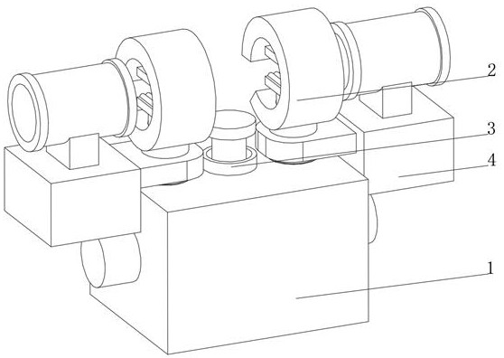
[0037] see Figure 1-Figure 3 , the present invention provides a technical solution: an on-line monitoring device for AC power transmission projects that is easy to maintain, specifically comprising:
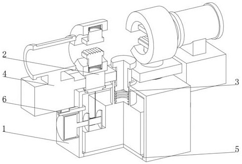
[0038] A monitoring box 1, a fixing device 2 is provided at both ends of the top of the monitoring box 1, a monitoring device 3 is fixedly connected to the inner wall of the monitoring box 1, and the top of the monitoring device 3 runs through the monitoring box 1 and extends to the top of the monitoring box 1;
[0039] An induction power-taking device 4, one side of the induction power-taking device 4 is fixedly connected to the side of the fixing device 2, the coil on the induction power-taking device 4 is installed on the transmission line, and the bottom of the induction power-taking device 4 is provided with a power plug;
[0040] A maintenance port 5, the maintenance port 5 is arranged at the bottom of the monitoring box 1, and the inner wall of the maintenance port 5 is fix...
Embodiment 2
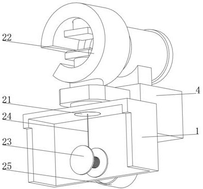
[0050] see Figure 1-Figure 4 On the basis of Embodiment 1, the present invention provides a technical solution: the chuck 22 includes a clamping ring 221, the top and bottom of the inner wall of the clamping ring 221 are provided with telescopic grooves 222, and the inner wall of the telescopic groove 222 is slidably connected with a telescopic rod 223 One end of the telescopic rod 223 is fixedly connected with a telescopic spring 224, and the end of the telescopic spring 224 away from the telescopic rod 223 is fixedly connected with the inner wall of the telescopic groove 222. An upper pressing plate 225 and a lower pressing plate 226 are provided, the top of the upper pressing plate 225 and the bottom of the lower pressing plate 226 are fixedly connected with the telescopic rod 223, the bottom of the clamping ring 221 is fixedly connected with the fixing seat 21 through a fixed rod, and the top of the lower pressing plate 226 is fixedly connected with friction One side of t...
Embodiment 3
[0052] see Figure 1-Figure 5 , on the basis of Embodiment 1 and Embodiment 2, the present invention provides a technical solution: the monitoring device 3 includes a monitor 31, the top of the monitor 31 is fixedly connected with a sliding sleeve 32, and the inner wall of the sliding sleeve 32 is slidably connected with a sealing piston 33, the top of the sealing piston 33 is fixedly connected with the ejector rod 34, the top of the ejector rod 34 is fixedly connected with the monitoring probe 35, the bottom of the sealing piston 33 is fixedly connected with the compression spring 36, and the monitor 31 is arranged inside the monitoring box 1 and connected with the monitoring box 1 The inner wall is fixedly connected, the top of the sliding sleeve 32 runs through the monitoring box 1 and is fixedly connected with the monitoring box 1, the monitor 31 is electrically connected with the monitoring probe 35 and the power socket 6, and a monitoring device 3 is provided. 24 drives ...
PUM
 Abstract
Description
Claims
Application Information
 - R&D
- Intellectual Property
- Life Sciences
- Materials
- Tech Scout
- Unparalleled Data Quality
- Higher Quality Content
- 60% Fewer Hallucinations
Browse by: Latest US Patents, China's latest patents, Technical Efficacy Thesaurus, Application Domain, Technology Topic, Popular Technical Reports.
© 2025 PatSnap. All rights reserved.Legal|Privacy policy|Modern Slavery Act Transparency Statement|Sitemap|About US| Contact US: help@patsnap.com


