
Design method of liquid rocket upper-stage storage tank anti-shaking device

A liquid rocket and design method technology, applied in design optimization/simulation, computer-aided design, calculation, etc., can solve the problems of large sloshing damping of the upper stage tank, reducing the carrying capacity of the rocket, increasing the quality of the rocket structure, etc. Body bearing capacity, simple and reliable structure, and the effect of reducing the welding seam

Pending Publication Date: 2022-05-20
AEROSPACE SCI & IND KET TECH CO LTD
View PDF0 Cites 2 Cited by
  • Summary
  • Abstract
  • Description
  • Claims
  • Application Information

AI Technical Summary

Problems solved by technology

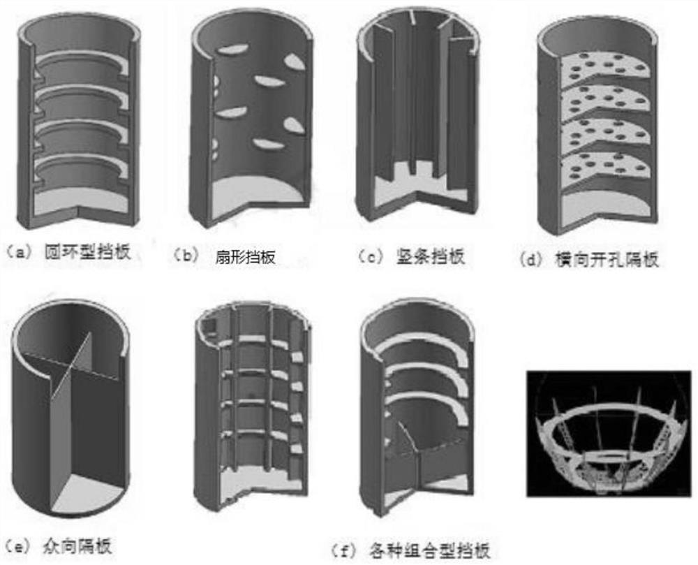
[0003] At present, the commonly used anti-sway plates include semi-circular anti-sway plates, circular anti-sway plates, vertical partitions, etc. Although the installation of anti-sway plates can effectively improve the sway damping, there must be a sufficient number of anti-sway plates to Reaching the stability control requirements will greatly increase the structural mass of the rocket, which will reduce the carrying capacity of the rocket to a certain extent. During the flight of the upper stage, the upper stage storage tank will also shake due to the influence of external excitation. Although the shaking mass is not large, because the upper stage shaking center of mass is far from the rocket body center of mass, the resulting shaking moment is relatively large, and its impact on the rocket body The impact of the attitude will even exceed the impact of the shaking of other storage tanks. Therefore, during the flight of the first stage of the rocket, the shaking damping of the upper storage tank is required to be large enough, and it is urgent to invent a new design scheme.

Method used


Image

  • Design method of liquid rocket upper-stage storage tank anti-shaking device
  • Design method of liquid rocket upper-stage storage tank anti-shaking device
  • Design method of liquid rocket upper-stage storage tank anti-shaking device

Examples


Embodiment Construction

[0043] The technical solutions in the embodiments of the present invention will be clearly and completely described below in conjunction with the accompanying drawings. Apparently, the described embodiments are only some, not all, embodiments of the present invention. Based on the embodiments of the present invention, all other embodiments obtained by persons of ordinary skill in the art without making creative efforts belong to the protection scope of the present invention.

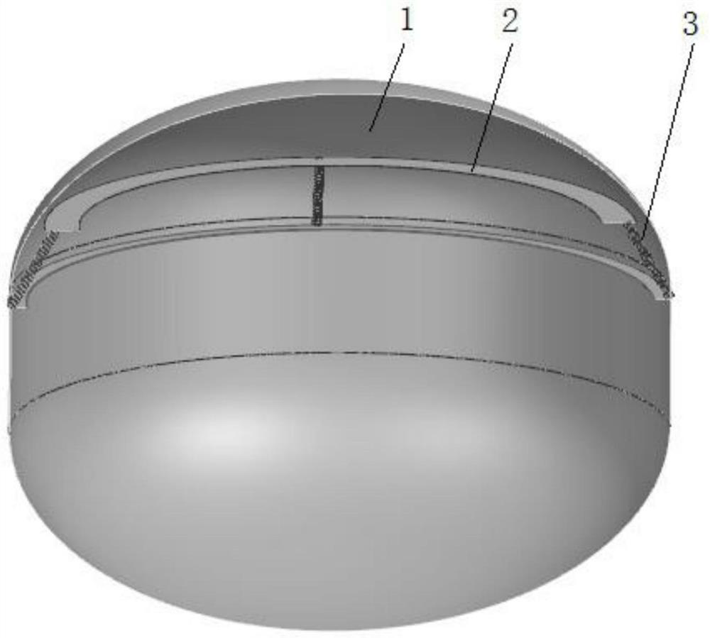
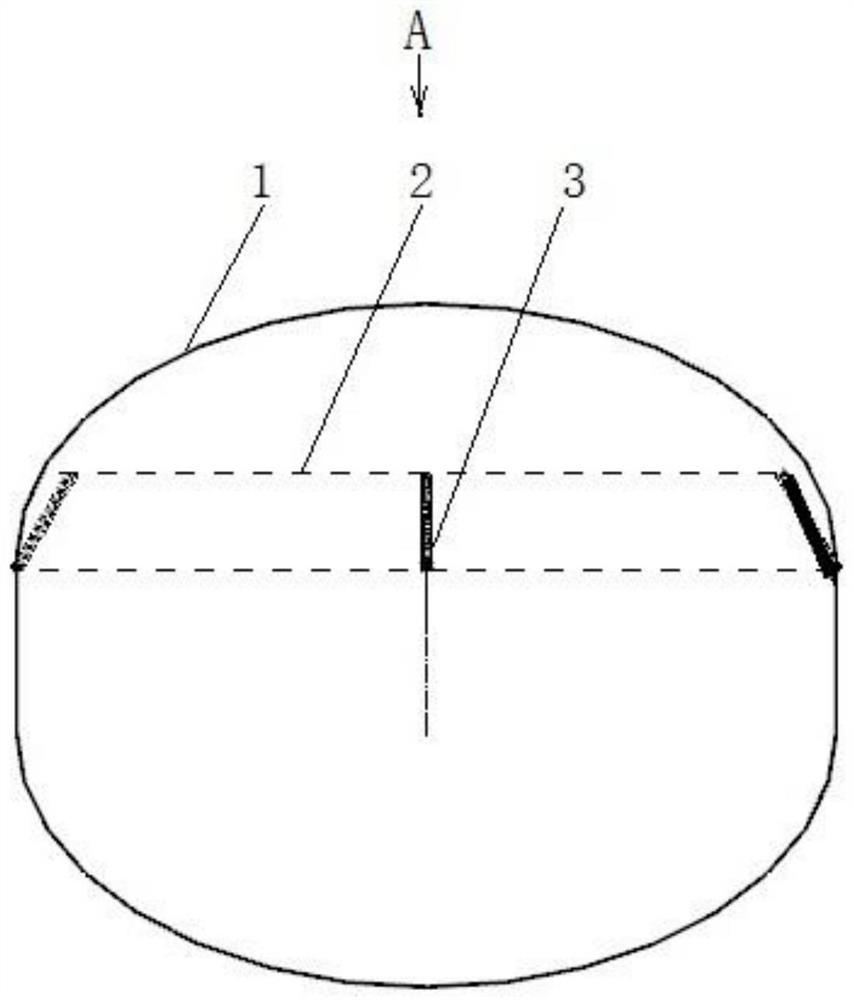
[0044] The design method of the anti-sway device for the upper stage storage tank of a liquid rocket of the present invention is based on the anti-sway structure of the spring-fixed anti-sway plate,

[0045] Including the following steps:

[0046] Determine the target sloshing damping value, the target value of this embodiment is not less than 8%;

[0047] Preliminary estimation of damping size;

[0048] The size of the slosh damping can be preliminarily estimated by the following formula:

[0049] ...


PUM


Abstract

The invention relates to a design method of an anti-shaking device for an upper-stage storage tank of a liquid rocket. Comprising the following steps: determining a target shake damping value; preliminarily estimating the damping size; the width of the anti-shaking plate is designed and adjusted, so that the corresponding damping magnitude is obtained; performing shake simulation analysis on the VOF multiphase flow through fluid simulation calculation software to obtain exact shake damping; the maximum shaking force is selected through shaking force data output through simulation, and a spring is selected. The anti-shake device has the advantages that high and stable shake damping can be provided within a wide liquid level range only through one anti-shake plate, the anti-shake device is simple and reliable in structure and easy to assemble, the mass of the anti-shake device is reduced, the carrying capacity of a rocket body is improved, weld joints are reduced, and the safety of an upper-stage storage tank is improved; and the design is quicker, the rapid iteration requirement is met, and the movable anti-shaking plate can be adjusted according to the requirement to meet different task requirements.

Description

technical field [0001] The invention relates to the anti-shake field of liquid launch vehicle storage tanks, in particular to a design method of an anti-sway device for liquid rocket upper stage storage tanks. Background technique [0002] In a large liquid launch vehicle, the liquid propellant occupies most of the mass of the rocket, and the liquid in the storage tank will slosh due to external excitations such as rocket body vibration, engine thrust change, and attitude adjustment during the flight. If certain measures are not taken to suppress the liquid sloshing, the liquid sloshing will affect the attitude of the rocket, and even cause mission failure in severe cases. In order to ensure the stability of the rocket during flight, measures must be taken to suppress the sloshing of the liquid. The current measures to suppress propellant sloshing are mainly to weld a certain number of anti-sway plates on the tank wall, so as to achieve the effect of improving sloshing damp...

Claims


Application Information

Patent Timeline
Patent Type & Authority Applications(China)
IPC IPC(8): G06F30/15G06F30/28G06F113/08G06F119/14
CPCG06F30/28G06F30/15G06F2113/08G06F2119/14Y02T90/00
Inventor 宋心成郑洪伟刘重洋田鹏宇兰薇薇刘访孙康刘力宇黄陈哲周前坤崔敏亮
Owner AEROSPACE SCI & IND KET TECH CO LTD
Learn More