Thread passing device in embroidery machine

An embroidery machine and thread-passing technology, which is applied to embroidery machines, embroidery machine mechanisms, textiles and papermaking, etc., can solve the problems of upper thread tension adjustment error, decline in embroidery quality, and change in elastic coefficient, and achieve accurate waxing and reduce The effect of fuzzing and wax reduction

Active Publication Date: 2022-05-24
南通佳利园纺织品有限公司
View PDF10 Cites 0 Cited by
  • Summary
  • Abstract
  • Description
  • Claims
  • Application Information

AI Technical Summary

Problems solved by technology

[0004] But there are still big defects in the prior art, as: 1, the tension force of the embroidery thread on different needles in the above-mentioned technology is to utilize pagoda spring to adjust simultaneously, can't adapt to the requirement of the embroidery thread on different needles to different tension force, causes The quality of embroidery is degraded, and the elastic coefficient of the pagoda spring will change after being used for a long time, which will cause errors in the tension adjustment of the upper thread; The upper thread is worn due to excessive friction during the conveying process, which affects the quality of embroidery

Method used


Image

  • Thread passing device in embroidery machine
  • Thread passing device in embroidery machine
  • Thread passing device in embroidery machine

Examples


Embodiment 1

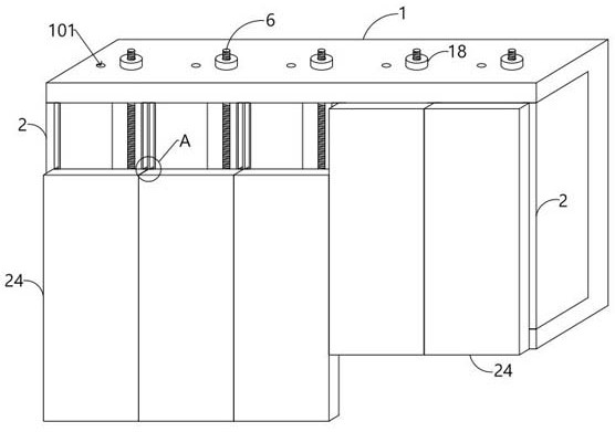
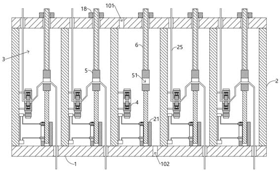
[0035] A thread-passing device in an embroidery machine, comprising a thread-passing box 1, a plurality of partitions 2 are vertically and equally spaced in the thread-passing box 1, and the partitions 2 divide the inner space of the thread-passing box 1 into a plurality of middle thread-passing cavities. 3. The setting of the partition plate 2 divides the wire passing box 1 into a plurality of middle wire passing chambers 3, so that the embroidery threads 25 are transported in the corresponding middle thread passing chambers 3, so as to prevent the embroidery threads 25 from interfering with each other and causing winding 2. To solve the problem of spooling and winding, the upper plate body of the wire-passing box 1 is provided with a wire inlet hole 101 that communicates with the middle wire-passing cavity 3, and the lower plate body of the wire-passing box 1 is provided with a wire outlet hole that communicates with the middle wire-passing cavity 3. 102. A rotating gear 4 wi...

Embodiment 2

[0041] The second embodiment increases the fixing effect of the tension adjusting rod 6 on the basis of the first embodiment, that is: the outer side of the tension adjusting rod 6 is provided with a threaded structure, and the end of the tension adjusting rod 6 extending out of the wire box 1 is threadedly connected with a lock. For the nut 18, when the tension adjustment rod 6 pulls the tension adjustment block 5 to move to a predetermined position, the locking nut 18 is sleeved on the tension adjustment rod 6, and the tension adjustment rod 6 is locked and fixed, which is simple and convenient.

Embodiment 3

[0043] The third embodiment discloses the rotation setting of the rotating gear 4 on the basis of the first embodiment, that is, the rotating gear 4 is provided with a sliding ring groove 43 for slidingly placing the limit block 20, and the limit block 20 is fixedly connected with a sliding extension. The support rod 19 of the rotating gear 4 is pulled out. The support rod 19 is fixedly connected to the inner wall of the middle wire cavity 3, and the rotating gear 4 is supported by the cooperation of the support rod 19 and the limit block 20, so that the rotating gear 4 can rotate stably. The limit blocks 20 are preferably two and symmetrically arranged, and the two limit blocks 20 are fixedly connected with the support rods 19 .


PUM


Abstract

The invention discloses a thread passing device in an embroidery machine, which comprises a thread passing box, the interior of the thread passing box is divided into a plurality of middle thread passing cavities by a plurality of partition plates, the thread passing box is provided with a thread inlet hole and a thread outlet hole which are communicated with the middle thread passing cavities, and a rotating gear and a tension adjusting block are arranged in each middle thread passing cavity. The waxing hole is connected with a wax feeding groove internally provided with a first magnetic plate, an elastic bag, a second magnetic plate and a wax block, a series circuit which is electrically connected with a power source through a wire, a driving motor and a resistance rod is arranged in the middle wire passing cavity, and the driving motor is provided with a driving gear. During use, the tension of the embroidery thread is adjusted by pulling the tension adjusting block, the embroidery thread is waxed by arranging the wax block, the embroidery effect of the embroidery thread is improved, the fixed power connection block and the sliding power connection block are arranged in a matched mode, and therefore the embroidery thread is more attractive in appearance and more attractive in appearance. Therefore, the waxing of the embroidery thread is more accurate and controllable.

Description

technical field [0001] The invention relates to the technical field of embroidery machine equipment, in particular to a thread passing device in an embroidery machine. Background technique [0002] The upper thread passing system on the embroidery machine is divided into upper, middle and lower thread passing systems. The upper thread passing system has a thread passing sleeve and a tension adjuster on the bobbin, while the middle thread passing system only uses thread passing holes. Due to the development of computerized embroidery machines from the original six-needle and nine-needle to the current fifteen-needle, that is, more and more embroidery threads, it is easy to wind and tangle the thread during the thread routing process, resulting in failures such as thread merging and thread breakage. It affects the normal operation of the machine and seriously affects the quality of embroidery. [0003] In the prior art, a thread-passing device for a computerized embroidery ma...

Claims


Application Information

Patent Timeline
Patent Type & Authority Applications(China)
IPC IPC(8): D05C11/08D05C11/10D05C11/24D02J3/18
CPCD05C11/08D05C11/10D05C11/24D02J3/18
Inventor 邱拥军
Owner 南通佳利园纺织品有限公司
Why Eureka
Try Eureka