
Bealock hole cast-in-place wall structure and construction method

A technology of cast-in-place walls and pass walls, which is applied to building structures, formwork/formwork/work frames, and on-site preparation of building components. It can solve the problems affecting the construction work and the construction process of aerated concrete block walls Many, irregular cracks and other problems, to achieve the effect of eliminating dust pollution on the construction site, reducing labor and material costs, and speeding up the construction progress

Pending Publication Date: 2022-05-24
XINJIANG SUZHONG CONSTR ENG
View PDF5 Cites 0 Cited by
  • Summary
  • Abstract
  • Description
  • Claims
  • Application Information

AI Technical Summary

Problems solved by technology

As a result, a series of quality problems such as horizontal cracks between the concrete frame beam and the aerated block filled wall, vertical cracks at the edge of the shear wall column, and irregular cracks in the wall appear.
3. There are many construction procedures for the aerated concrete block wall, the construction is difficult, and the overall construction cost is high
In addition, during the transportation of blocks and plastering materials, a large number of lifting machinery workbenches will be occupied, which will affect the development of other follow-up construction operations, and thus affect the construction progress of the entire project.

Method used


Image

  • Bealock hole cast-in-place wall structure and construction method
  • Bealock hole cast-in-place wall structure and construction method
  • Bealock hole cast-in-place wall structure and construction method

Examples


Embodiment 1

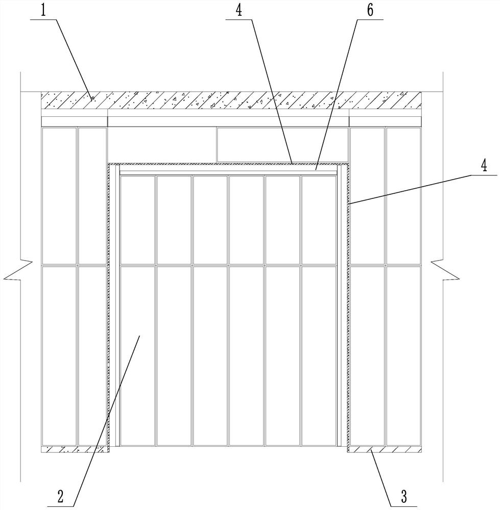
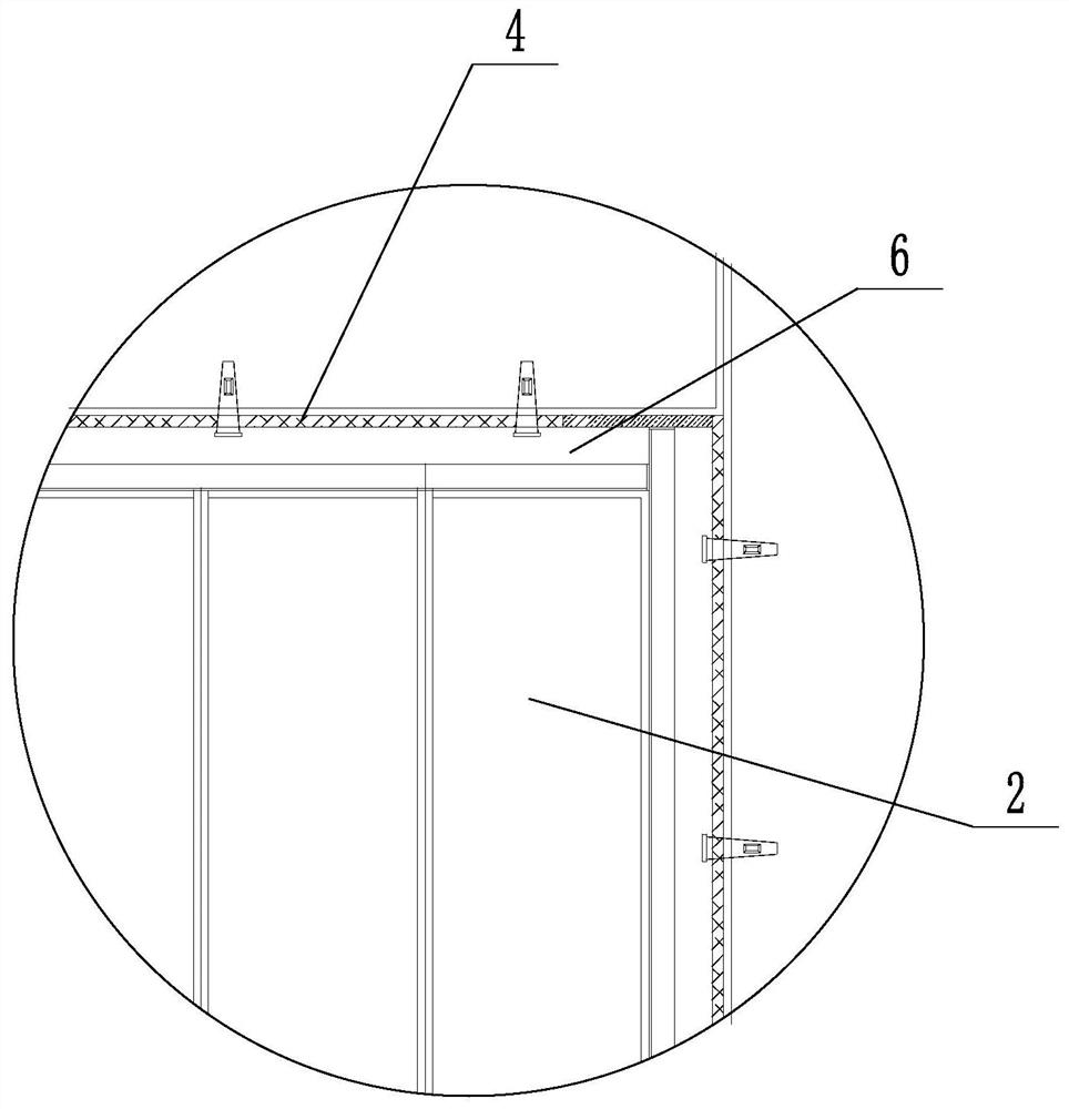
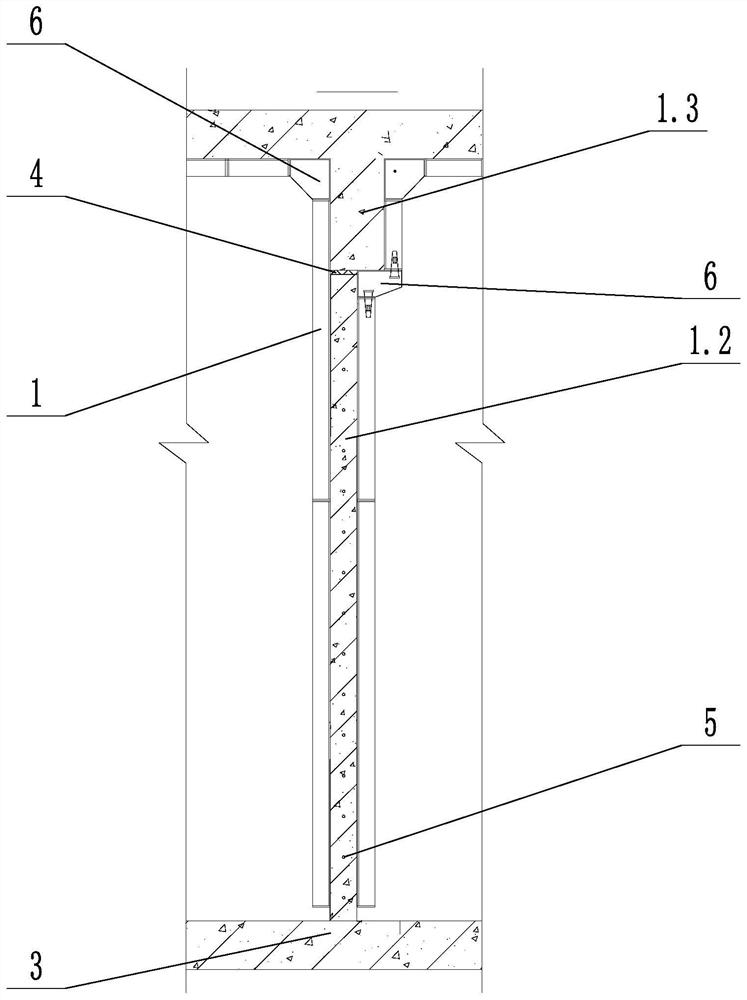
[0033] like figure 1 , figure 2 , image 3 and Figure 4 As shown, a kind of cast-in-situ wall structure of a pass hole comprises a cast-in-place wall 1, a formwork 2 and a base plate 3, the cast-in-place wall 1 and the formwork 2 are arranged above the base plate 3, and the cast-in-place wall 1 is arranged in the formwork 2; The cast-in-place wall 1 includes a pass wall 1.1, a shear wall 1.2 and a frame beam 1.3. A wood wool board 4 is provided between the pass wall 1.1 and the shear wall 1.2, and a wood wool board is provided between the pass wall 1.1 and the frame beam 1.3. 4. The wood wool board 4 is fixed with the formwork 2, and a pouring hole 4.1 is provided on the wood wool board 4 between the pass wall 1.1 and the frame beam 1.3. The pass wall 1.1 is provided with a single-layer two-way reinforcing mesh sheet 5, and the ends of the two-way reinforcing mesh sheet 5 pass through the wood wool board 4 and are bound and connected with the main reinforcement in the sh...

Embodiment 2

[0036] A construction method for a cast-in-place wall of a Yakou cave, which adopts the above-mentioned cast-in-situ wall structure of a Yakou cave, comprising the following steps:

[0037] a. Reinforcing bar bundling: Bind the reinforcing bars at the position where the cast-in-place wall 1 needs to be poured, and at the same time place the wood wool board 4 at the set position; when the reinforcing bars are bundled, the single-layer two-way reinforcing mesh sheet 5 is used in the entrance wall 1.1. The ends of the steel mesh in 1.1 pass through the wood wool board 4 that is in contact with the wall, and the steel bars are inserted into the shear wall 1.2 at both ends and the top frame beam 1.3 to bind and connect with the main reinforcement of the structure;

[0038] b. Formwork fixing: fix the formwork 2 on the outside of the cast-in-place wall 1 to be poured, and fix the wood wool board 4 on the formwork 2;

[0039] c. Layered pouring: pour the pass wall 1.1 and the shear w...


PUM


Abstract

The invention discloses a bealock cast-in-place wall structure and a construction method, the bealock cast-in-place wall structure comprises a cast-in-place wall body, a template and a bottom plate, the cast-in-place wall body and the template are arranged above the bottom plate, and the cast-in-place wall body is arranged in the template; the cast-in-place wall body comprises a bealock wall, a shear wall and a frame beam, a wood-wool plate is arranged between the bealock wall and the shear wall, a wood-wool plate is arranged between the bealock wall and the frame beam, the wood-wool plate is fixed to the formwork, and a pouring hole is formed in the portion, between the bealock wall and the frame beam, of the wood-wool plate. The invention provides a bealock cast-in-place wall structure and a construction method. The bealock cast-in-place wall structure has the advantages of being more convenient to apply, higher in safety, higher in economical efficiency, higher in construction speed, better in environmental protection performance and the like.

Description

technical field [0001] The invention relates to the technical field of construction, in particular to a cast-in-place wall structure and a construction method for a Yakou cave. Background technique [0002] In traditional house construction projects, the treatment method between the shear walls and the openings is to use autoclaved aerated concrete blocks for secondary masonry, and the surface is hung with wire mesh plastering treatment. This approach has the following disadvantages: [0003] 1. The aerated concrete block infill wall adopts secondary masonry construction, which affects the integrity of the wall, and the surface forming effect is not good. The surface of the wall needs to be treated with secondary plastering. Due to the large porosity of the aerated concrete block material itself, the water absorption speed is fast, and it is easy to absorb the moisture of the plastering mortar, resulting in a large amount of water loss on the plastering surface, the cement ...

Claims


Application Information

Patent Timeline
Patent Type & Authority Applications(China)
IPC IPC(8): E04G11/06E04G17/00E04G21/02E04G21/06
CPCE04G11/06E04G17/001E04G21/02E04G21/06
Inventor 顾李平林荣麻黎
Owner XINJIANG SUZHONG CONSTR ENG
Learn More