Track fault diagnosis simulation experiment track device
A technology of fault diagnosis and simulation experiment, applied in the direction of measuring devices, testing of machine/structural components, instruments, etc. Effect
- Summary
- Abstract
- Description
- Claims
- Application Information
AI Technical Summary
Problems solved by technology
Method used
Image
Examples
Embodiment 1
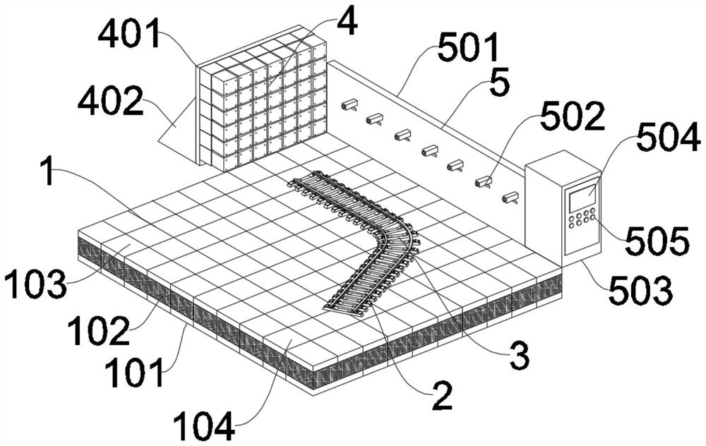
[0031] Please refer to Figure 1, a track fault diagnosis simulation experiment track device, including a foundation 1, a track is laid on the top of the foundation 1, the track is formed by splicing a straight rail 2 and a curved rail 3, and an impact test device 4 is installed on the top of the foundation 1 , the impact test device 4 is located at the end of the track, and a detection device 5 is installed on the top of the foundation 1, and the detection device 5 is located on the side of the track.
[0032] The foundation 1 includes a base 101 , the top of the base 101 is filled with a filling material 102 , and a top plate 103 is installed on the top of the filling material 102 .
[0033] The filling material 102 is composed of common track bed materials such as soil and small stones.
[0034] In the present invention, the foundation 1 under the track is specially designed. The foundation 1 includes a base 101, the top of the base 101 is filled with a filling material 102,...
Embodiment 2
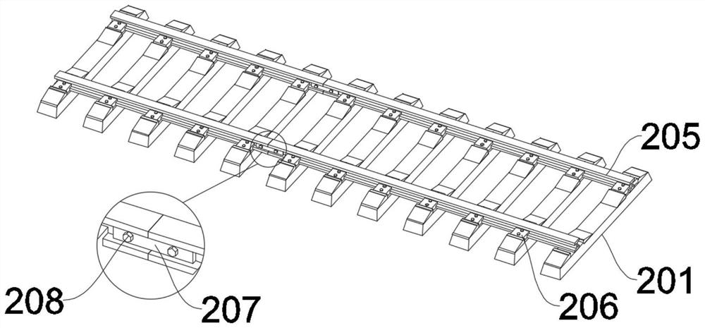
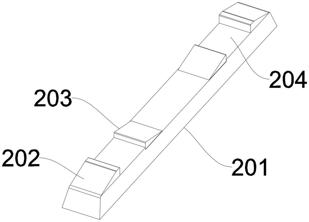
[0036]Referring to Figures 2-5, the basic difference in combination with Embodiment 1 is that the straight rail 2 includes several sleepers 201, the sleepers 201 are laid in parallel on the top of the pressure-bearing module 104, and the tops of both ends of the sleepers 201 are welded There is an outer clamp 202, an inner clamp 203 is welded on the top of the sleeper 201, a track groove 204 is arranged between the outer clamp 202 and the inner clamp 203, the straight rail 2 also includes several linear rails 205, several linear rails 205 Spliced together and located above the track groove 204, a fixed iron piece 207 is connected to the outside of the gap between the two linear steel rails 205, and a bolt 208 is inserted on the inner side of the fixed iron piece 207, and the bolt 208 penetrates the side of the linear steel rail 205, A connection fitting 206 is threadedly connected to the top of the track groove 204 , and the connection fitting 206 is threadedly connected to t...
Embodiment 3
[0040] Referring to FIG. 6, the difference between the first and second embodiments is that the impact test device 4 includes a bumper plate 401, the back of the bumper plate 401 is fixedly connected with a support plate 402, and the front side of the bumper plate 401 is welded There are several shells 403, an electric push rod 404 is threadedly connected to the inner wall of the rear end of the shell 403, the front end of the electric push rod 404 is connected with an inner lining 405, the inner lining 405 is inserted in the front end of the outer shell 403, and the front end of the inner lining 405 is provided with Fixing holes 406 . The impact test device 4 also includes several connecting plates 407 . The surfaces of the connecting plates 407 are welded with special-shaped blocks 408 of different shapes.
PUM
 Abstract
Description
Claims
Application Information
 - R&D
- Intellectual Property
- Life Sciences
- Materials
- Tech Scout
- Unparalleled Data Quality
- Higher Quality Content
- 60% Fewer Hallucinations
Browse by: Latest US Patents, China's latest patents, Technical Efficacy Thesaurus, Application Domain, Technology Topic, Popular Technical Reports.
© 2025 PatSnap. All rights reserved.Legal|Privacy policy|Modern Slavery Act Transparency Statement|Sitemap|About US| Contact US: help@patsnap.com


